A feature of this version is the old-style E-I type transformer and original style transistors. It gives the amplifier an original appearance inside but that won't improve the sound. On the other hand, cooling may be a little better than other versions, which will be good, since the whole amplifier will become quite warm to touch after an hour or so.
Suggestion: Elevate the amplifier above the surface it sits on to allow plenty of free air flow from below the heatsinks.
I couldn't find a translation option for the Russian article you linked but the differences have been discussed many times in this thread. Essentially, it now has a dual rail power supply which allows the output capacitor to be eliminated. Accordingly, the DC offset and bias controls are also improved. The history of the various versions and other worthwhile modifications is here: The Class-A Amplifier Site
To get perfect balance needs 100K upper and 120K lower DC setting resistors ( perfectly with the maths ). This will vary with device and grade. My BC327/337 show> 400 on cheap hfe tester.
Hi all,
is there someone who can explain how to calculate lower resistance value ?
Thank you.
What I did was fix one resistor and play with the other. What I like about the JLH is it will give you enough time to set up mid voltage without trouble. I was using a linear regulated PSU which helps. Even though I don't like SMPS they are worth having for set up as they switch off if overloaded. Exact voltage does matter with JLH. Not the absolute voltage, Just be careful not to allow it to change once chosen. If you buy a SMPS have the exact current it needs or a little over. If you want better make a regulated linear supply. I see no reason not to have a large transformer if linear. 2x LM317 can work well as they have internal current limiting that might be useful. 1.5 Amps at a guess. Makes differ so read spec sheets.
I asked this question because I'm currently using this kit :

When I tried to adjust the voltage, the trimmer (100K, left on the picture) was not sufficient to have 1/2 V between transistors. R4 is 75K in the kit (instead of 100K) and the original 39K is 10K. The correct value for R5 with these values seems around 104K. I put 103K, but voltage is not yet symmetric.
JLH in his 1970 article fixed R4 and R5 to 100K and replace 39K with 12K.
He wrote "The necessary value of resistors R5 and R6 to give an entirely adequate accuracy in the mid-point voltage setting can be predicted, and the suggested amended values are shown."
I work now on a second version of the amp, and I'd want to calculate the value of R5. I can put a trimmer, fix voltage, unsolder... But it's not really easy with metalized holes on the pcb (I damaged the pcb I'm currently using when I unsoldered the 100K trimer). So I asked if somenone know the calculation.
I used a SMPS for this kit (300W 2x24V SMPS300RS | Connex Electronic) Sound was very good. But sound is fabulous with a linear power supply like the one used by Andrea Ciuffoli for his power follower.
Calculating isn't easy (due to current gain differences between transistors) but the values needed are derived empirically like this...
The emitter of the first transistor (TR4) will be around one volt less than the midpoint voltage needed. How do we know that ? Because the current in TR4 is around 350 to 400uA which would drop around a volt across the 2700 ohm. The voltage across the 8.2k is the total of the two base/emitter volt drops of the two lower transistors. Say a total of 1.5 volts. That gives a current of about 180uA in the 8.2k and a similar current will be flowing to the base of the driver transistor give or take... depending on the gain of the devices used. So two times 180uA is 360uA total which is in the ballpark mentioned above (350 to 400uA).
From there we can say that the base of TR4 will be another 0.7 volts lower than the emitter (the standard Vbe volt drop for a silicon transistor). So we will need to set a voltage on TR4 base of around 10.3 volts if running on 24 volt rails.
10.3 volts gives us a definite voltage to aim for with the resistor network and so the resistor values can be calculated. If R5 is 100k then we need a current of I=V/R which is 10.3/100,000 which is 0.000103A or 0.103 milliamps or 103uA.
The two other series resistors, R6 and what was the original 39k therefore need to drop 24-10.3 which is 13.7 volts. Ohms law then gives us a total value for these two of 13.7/0.000103 which is 133009 ohms.
How you split that value is up to you") but the original 39k seems a fair choice. If you did that then R6 would need to be 133009-39000 which is 94k
but the original 39k seems a fair choice. If you did that then R6 would need to be 133009-39000 which is 94k
So the original values seem close to the mark... even more so when you account for the fact that the base current of TR4 will syphon of a tiny bit of current from the divider chain.
You can flip that calculation around and say that the 39k and upper 100k are fixed. We know 24 volts is applied to one end of the chain and that we need 10.3 on the transistor base.
We have a current of (24-10.3)/139000 which is 9.85E-5 or 98.5uA.
So R5 needs to be 10.3/9.85E-5 which is 104568 ohms. Again we have discounted the tiny base current of TR4 as it has minimal impact on the calculation.
So you can see the original values are pretty much ideal.
The emitter of the first transistor (TR4) will be around one volt less than the midpoint voltage needed. How do we know that ? Because the current in TR4 is around 350 to 400uA which would drop around a volt across the 2700 ohm. The voltage across the 8.2k is the total of the two base/emitter volt drops of the two lower transistors. Say a total of 1.5 volts. That gives a current of about 180uA in the 8.2k and a similar current will be flowing to the base of the driver transistor give or take... depending on the gain of the devices used. So two times 180uA is 360uA total which is in the ballpark mentioned above (350 to 400uA).
From there we can say that the base of TR4 will be another 0.7 volts lower than the emitter (the standard Vbe volt drop for a silicon transistor). So we will need to set a voltage on TR4 base of around 10.3 volts if running on 24 volt rails.
10.3 volts gives us a definite voltage to aim for with the resistor network and so the resistor values can be calculated. If R5 is 100k then we need a current of I=V/R which is 10.3/100,000 which is 0.000103A or 0.103 milliamps or 103uA.
The two other series resistors, R6 and what was the original 39k therefore need to drop 24-10.3 which is 13.7 volts. Ohms law then gives us a total value for these two of 13.7/0.000103 which is 133009 ohms.
How you split that value is up to you
but the original 39k seems a fair choice. If you did that then R6 would need to be 133009-39000 which is 94kSo the original values seem close to the mark... even more so when you account for the fact that the base current of TR4 will syphon of a tiny bit of current from the divider chain.
You can flip that calculation around and say that the 39k and upper 100k are fixed. We know 24 volts is applied to one end of the chain and that we need 10.3 on the transistor base.
We have a current of (24-10.3)/139000 which is 9.85E-5 or 98.5uA.
So R5 needs to be 10.3/9.85E-5 which is 104568 ohms. Again we have discounted the tiny base current of TR4 as it has minimal impact on the calculation.
So you can see the original values are pretty much ideal.

Thank you very much Mooly !
@mooly Thanks for this detailled explanation. I'll need to reread it tomorrow morning... And I'll do some calculations with the values of the kit.
@huggygood I used an ampere meter and a volt meter to check current and voltage. Voltage : between collector of left 2SA1216 and ground. Amperage : ampere meter in serial between power supply and vcc+.
With 75K and 10K of the kit, I found that R5 needs to be more than 100K (with the tolerance of the trimmer, it could be ok, but mine was short on value). With the explanation of mooly (thanks again) I'll do the maths tomorrow and report.
Believe me。 I made it.
But I don't recommend it.
The bass is very poor
Hi,
what voltage rail and bias current did you use ? With what speakers ?
With 75K and 10K of the kit, I found that R5 needs to be more than 100K (with the tolerance of the trimmer, it could be ok, but mine was short on value). With the explanation of mooly (thanks again) I'll do the maths tomorrow and report.
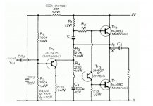
We need to be very clear that the resistor reference numbers in your kit agree with the JLH69 diagrams.
R5 was the 100k to adjust the midpoint voltage, R6 was a 100k above it and the 39k had no reference number.
If R6 and 39k in this diagram are in fact 75k and 39k then you will find that R5 needs to be lower, probably around 91k
Attachments
Hi Mooly,
the kit is not on the same schema as the original design, because 2SA1216 are PNPs and not NPNs. But I have the original article of JLH and yes, we are talking about R4, R5 and 39K of the origib=nal schema.
I reverse the pcb of the kit (no schema given with the kit), and draw this schema : (I perhaps made errors)
Resistors are in this schema R8, R9 and R10. With this schema, R10 needs to be more than 100K.
the kit is not on the same schema as the original design, because 2SA1216 are PNPs and not NPNs. But I have the original article of JLH and yes, we are talking about R4, R5 and 39K of the origib=nal schema.
I reverse the pcb of the kit (no schema given with the kit
), and draw this schema : (I perhaps made errors)An externally hosted image should be here but it was not working when we last tested it.
.jpg)
Resistors are in this schema R8, R9 and R10. With this schema, R10 needs to be more than 100K.
Last edited:
Hi,
what voltage rail and bias current did you use ? With what speakers ?
the thing with the JLH is that it will always work, no matter what its configuration.
but to make it work well, you have to take the time to select the components and work on a power supply .
I have assembled a little over 10 and they are all different, they each have their own personality,I even had fun changing the transformer several times on the same amp and on the 69th, one can "hear" the difference very clearly.
the 69 remains my favorite
try with a 250k lin potentiometer .An externally hosted image should be here but it was not working when we last tested it.
Resistors are in this schema R8, R9 and R10. With this schema, R10 needs to be more than 100K.
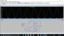
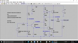
2SA1216 are here replaced by 2SA1386 because my next version of this amplifier will be using these.
why have you choose c2240 and a1145 ?
I agree, this amplifier is really transparent. I did not use all the parts that came with the kit. And I'm working now on the power supply. The SMPS I used was the easy way to put all this in on. Now, with the experience of this first attempt, I plan to made a second version.
Last edited:
The jlh69 is great amp.
Imprtant is the powesupply.
The bias of mine amplifier is 2A (30V)
Speakers are 94db .
Bass is is more than enough.
Hi, what's the impedance of your speakers ?
- Home
- Amplifiers
- Solid State
- JLH 10 Watt class A amplifier