Hi Mooly,
the kit is not on the same schema as the original design, because 2SA1216 are PNPs and not NPNs. But I have the original article of JLH and yes, we are talking about R4, R5 and 39K of the origib=nal schema.
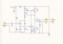
I reverse the pcb of the kit (no schema given with the kit), and draw this schema : (I perhaps made errors)
Resistors are in this schema R8, R9 and R10. With this schema, R10 needs to be more than 100K.
That's an interesting take on the design because normally if you change a design from NPN to PNP (the outputs) you would also change the design to positive earth, which this doesn't seem to do. +24 volts would become ground, and the amp would operate on a negative 24 volt rail.
Its a subtle difference but could be quite important to the way the amplifier deals with hum/ripple on the rails.
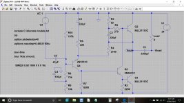
I do have a PNP simulation from ages ago and it should look like this. The rail is now a negative value, 27 volts in this case.
Attachments
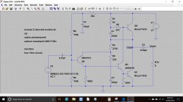
What's disturbed me is that when I draw the schema, R4 and C3 of the original JLH are on the same side of the circuit as C1 and R3. I looked twice, but on the pcb, (R1, C1) and (R4, C3) are connected to ground in parallel, divided by the 2.7K R3 (all the references are ones of the orignal JLH69 schema)
FredG,
Impedance speakers are(nomnal) 8 OHM
For tight bass you wil use a good psu
- 2x trafo 24v/160V
- 2x 4700uf Hammond 10mh2x4700uf
In mine opinion (experiance) are this minimal numbers for a proper set up
The greatest strenght of the original are the mids and hights
I like it as a gread (addicting) performer
Yes
For good class a amplifier you need big psu and cooling
Designes of Nelson pass are going the same way
I dont like the multiplier set up
In comparison it lacks strenght and speed
OK. Thank you.
The multiplier can be lightning fast. Use a FET. The JLH is circa 160 kHz so even the cheapest Darlington will be fast enough. The biggest thing is this is a class A amp. The need for speed is minimal. In fact the need for speed is about 2 kHz as the line decoupling capacitor ( often 220 uF ) can do the fast things. 2 kHz usually will deal with 50 Hz ripple. A FET is mostly a resistor which has gain. Very cheap also.
What's disturbed me is that when I draw the schema, R4 and C3 of the original JLH are on the same side of the circuit as C1 and R3. I looked twice, but on the pcb, (R1, C1) and (R4, C3) are connected to ground in parallel, divided by the 2.7K R3 (all the references are ones of the orignal JLH69 schema)
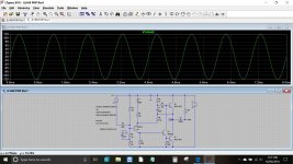
This shows your version. Remember that in simulation, the rails are perfect and so both ground and the rail are at the same impedance as far as AC signals are concerned. One possible problem with a real build would be that the bootstrap cap and resistor currents would not have to interfere with the input ground current.
In the positive earth version that issue doesn't exist.
The whole concept of the amp is subtly changed by this arrangement (your diagram) as such things as the collector load resistor for Q4 (8k2) is now able to have ripple and noise from the PSU directly injected into it whereas before it was at ground potential. The same applies to R2, this is now returned to a 'noisy' point of the circuit rather than ground.
In practice this will change the nature of the distortion of the amp, with the changes altering with output current. It also makes the PCB layout far more critical to minimise these problems.
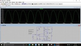
Your version and the positive earth version showing how simulated 100Hz ripple on the PSU is changed in character. The positive earth version is much less spiky in nature, your version passes the ripple through pretty much as it appears on the rail. At HF (SMPS) it could be worse.
Attachments
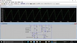
Your version and the positive earth version showing how simulated 100Hz ripple on the PSU is changed in character. The positive earth version is much less spiky in nature, your version passes the ripple through pretty much as it appears on the rail. At HF (SMPS) it could be worse.
It's perhaps the reason why the sound is better with a linear power supply than with the SMPS I used before... Even if this SMPS is a good one.
Nevertheless, to my ears and with the linear power supply, the sound of this kit is really good.
I tried your maths on the schema, but I don't managed to calculate R10 value. On your simulation, I see that the good value is 107K, in theory.
With an increased rail voltage, how this value change ?
Lower values will change the ratio of ac/dc current running through the spliter transistor. (not really ac but the "audio" fluctuation; here versus the "standing" current). So yes harmonics ("tone") and "speed" (how fast the base charge of the outp. transistors decreases).
The bootstrap cap at 220uF into 82R||270R (=cca 63R "load") bootstrap resistors is a joke. 680uF would be better, 470uF at minimum.
The bootstrap cap at 220uF into 82R||270R (=cca 63R "load") bootstrap resistors is a joke. 680uF would be better, 470uF at minimum.
I tried your maths on the schema, but I don't managed to calculate R10 value. On your simulation, I see that the good value is 107K, in theory.
With an increased rail voltage, how this value change ?
24 volt supply, midpoint of 12 volts. The emitter of Q4 will higher than this by around 1 volt. It is higher this time because have flipped all our polarities of transistors. The base voltage needed will therefore be around 12+1+0.7 which is 13.7 volts. Remember for an NPN the base is 0.7 volts or so higher than the emitter, for the PNP it is 0.7 volts lower.
75k and 10k give the equivalent of an 85k resistor and we know now that one end will be a 24 volts and the other at 13.7 volts. That means 10.3 volts is dropped across the 85k giving a current of 0.121 milliamps.
From there we can say that for our unknown resistor we need a value of 13.7/0.121E-3 which is 113k. In practice the simulation worked best (most symmetrical clipping) with a 107k. Its close though.
With an increased rail voltage, how this value change ?
Lets try it. This shows stepped values of supply up to 40 volts. It tracks pretty well if you read off the supply voltage and then look at the midpoint voltage.
Attachments
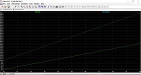
Lets try it. This shows stepped values of supply up to 40 volts. It tracks pretty well if you read off the supply voltage and then look at the midpoint voltage.
Thank you very much for your help Mooly.
Hi,
what voltage rail and bias current did you use ? With what speakers ?
More than 50% of China's 1969. I sold it all.
The number is more than 1K. I've tested it, but I'm not going to talk about it.
Because I don't like to say bad things. I never recommended it, though I sold a lot.
If you have an instrument for measurement, you will know.
A good amplifier does not need to be adjusted, nor does it require special power supply.
Adjust. Special power supply, special sound box.
In my opinion, it's just an excuse for poor performance.
1969 in my opinion, even cannot be called a qualified products.
No company in the use of the circuit.
And I'm in my sales of 1969 on the PCB. Did not suit the LOGO.
Because I don't want to let others think that this is the design of the suit.
In my opinion, the CLASS A is just A useless message.
Attachments
Last edited:
But it's not really easy with metalized holes on the pcb (I damaged the pcb I'm currently using when I unsoldered the 100K trimer). So I asked if somenone know the calculation.
.
You could put thin wires onto the trimmer and just solder the wires to the top side of the hole without filling in the via with solder.
Then its easy to remove the wires and use set resistors.
You could put thin wires onto the trimmer and just solder the wires to the top side of the hole without filling in the via with solder.
Then its easy to remove the wires and use set resistors.
Not a bad idea.
The other idea I had is to use 3 independants sockets like this one (I have them on stock) H3192-01 | Discrete Socket, HARWIN 2A serie H31 | HARWIN You can plug and unplug the trimmer to adjust and measure it. Then you put resistor in place and solder the resistor with the socket.
Also remember that the midpoint voltage isn't all that critical. For example (and based on the simulation) when correctly set you may get around 8.22 vrms into 8 ohm. Now lets offset the midpoint to say 10.4 vdc by making the 107k resistor into an 82k. We now get around 7.4 vrms into 8 ohms before clipping. Power wise that is 8.4 watts rms vs 6.8 watts rms.
You would be unlikely to tell any difference in practice.
You would be unlikely to tell any difference in practice.
- Home
- Amplifiers
- Solid State
- JLH 10 Watt class A amplifier