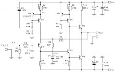
I made my first ever pcb layout today for the JLH 96 amplifier. I hope it is any good. Suggestions and comments are welcome.
Some notes:
R10 is off the pcb because this one gets hot.
The routes can be substantially bigger.
It isn't very neat.
Some Transistors have wrong device numbers.
But besides these points, would it work?
Some notes:
R10 is off the pcb because this one gets hot.
The routes can be substantially bigger.
It isn't very neat.
Some Transistors have wrong device numbers.
But besides these points, would it work?
Attachments
Hi LaZarus,
You may have to give us better/clearer overlay part number in order to make any sense out of it. In my experience the R10 just get a little warm, not hot to touch, what Iq are you setting it to?
I can not see where, how the R6 connect to signal ground.
Regards,
Chris
P.S. What version of 1996 JLH are you referring to?
What is that R11 2k2?
I have used this schematic, the updated '96 version.
Is it better to use a ground plane on my pcb layout, which will be connected to a star ground on my chassis, or an other grounding topology?
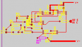
Here is my revised pcb layout.
An externally hosted image should be here but it was not working when we last tested it.
Is it better to use a ground plane on my pcb layout, which will be connected to a star ground on my chassis, or an other grounding topology?
Here is my revised pcb layout.
An externally hosted image should be here but it was not working when we last tested it.
LaZarus said:Ok, above is my new pcb layout, with wider tracks, place for a bigger capacitor and some other changes.
Any suggestions are still welcome.
btw, the decoupling C's still have to be added.
cheers
Hi,
Depending on your grounding scheme. The way I would do it IMO is to group the signal grounds(R2,C2,R6) and group the dirty grounds(R11,R12,C6,C7) separately. Each group then join to the star ground.
Regards,
Chris
Chris,
Thank you for your comments. About your previous post, can you please specify why I should place it behind Q1 and Q2?
I wil have to get a good look at it later this week, but can you please exlain what the theory is?
I have another question about the VA ratings of x-former. Nexus you run it from 2 120 VA transformers, but I also read about 450 VA's, which would be a bit expensive for me. I am planning to build this amp on a tight budget, just because I have to
Cheers.
have another question about the VA ratings of x-former. Nexus you run it from 2 120 VA transformers, but I also read about 450 VA's, which would be a bit expensive for me. I am planning to build this amp on a tight budget, just because I have to
Hello,
I use 2 transformers of 2x12VAC-120VA, this is 5A per coil.
I bias my amp with 1.2 to 1.5 A, this means approximately 8 Watts in audio power, so in this case there is no need for a higher rated transformer.
So the power rating of the used transformer simply depends on the amount of output power you want out of your amplifier.
Best Regards.
LaZarus said:Chris,
Thank you for your comments. About your previous post, can you please specify why I should place it behind Q1 and Q2?
Cheers.
Hi,
Please check section(5.6 DISTORTION 6: Induction from supply rails) at Douglas Self's web site
http://www.dself.dsl.pipex.com/ampins/dipa/dipa.htm#4
That was the experiment I tried with my JLH with positive result.
Regards,
Chris
PS: of course I take it for granted that I trust Doug Self is right in the first place because I have no EE background. Many experienced EE/diyer don't trust or question what others telling them thingies. So you are on your own to decide and filter thru vast amount of information in this world. May the force be with you that is only if you believe in the force in the first place. Yeah why people say God bless you to other people that they do not even know whether they believe in God or the same God?
Self's Distortion 6
Since the JLH amp we're talking about is a
Class A design, the "halfwave-rectified
currents" that Self is concerned about don't
come into play. (That was a distortion peculiar
to the class B output stage.)
Therefore the feedback pickup point isn't as
critical.
eL
Since the JLH amp we're talking about is a
Class A design, the "halfwave-rectified
currents" that Self is concerned about don't
come into play. (That was a distortion peculiar
to the class B output stage.)
Therefore the feedback pickup point isn't as
critical.
eL
Re: Self's Distortion 6
Hi,
Could that be I have made mistakes wiring up my JLH so that it may not be actually running in Class A mode? For sure to me anyway the mod of the feedback pick off point in my amps produced even darker background and overall clarity to the sound.
Regards,
Chris
eLarson said:Since the JLH amp we're talking about is a
Class A design, the "halfwave-rectified
currents" that Self is concerned about don't
come into play. (That was a distortion peculiar
to the class B output stage.)
Therefore the feedback pickup point isn't as
critical.
eL
Hi,
Could that be I have made mistakes wiring up my JLH so that it may not be actually running in Class A mode? For sure to me anyway the mod of the feedback pick off point in my amps produced even darker background and overall clarity to the sound.
Regards,
Chris
JLH feedback take-off point
Chris,
When I reconnected the feedback take-off point in my circuit in line with Doug Self's recommendations, the result was a similar improvement to what you have described. I found it surprising at the time, so much so that it made me think of the pros and cons of extending the take-off point to the terminals on the speakers! I suppose this demonstrates the the sensitivity of the n.f.b. loop.
Tim.
Hi Lazarus,Originally posted by LaZarus I have another question about the VA ratings of x-former. Nexus you run it from 2 120 VA transformers, but I also read about 450 VA's, which would be a bit expensive for me. I am planning to build this amp on a tight budget, just because I have to
Cheers.
I run my 1996 version rail of 22V @ 1.9A bias from a 225VA toriod for each channel.
I'm now building the 2003 version (28.5V rail @ 2.8A bias) and use a 330VA toriod for each version.
One is finished
 and under test now.
 A suggestion is to buy one "big" toriod now and run both channels for the time being from this one. You can upgrade later.
- Home
- Amplifiers
- Solid State
- JLH 10 Watt class A amplifier