Iq CCS
Miki,
In passing, I would clarify your recent point, the 2K preset is replaced with a 200R preset only when the feedback capacitor is removed, not necessarily when VR3 is included in the circuit, though in most cases the two would probably come together anyway.
General comment,
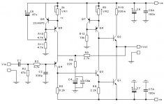
During my recent voyage of discovery when trying to track down the cause of noise/oscillation in my circuit, it was suggested to me by Geoff that R12 (Iq CCS) be reduced from 10K to between 1K8 and 2K7. Briefly, the reasons for this were that if the output transistors and Q8 have low gain, and depending on grounding arrangements for the offset CCS, the Iq CCS possibly might not operate reliably. It is my understanding that to reduce the value of R12 to that mentioned above would be prudent in any case.
Tim.
Miki,
In passing, I would clarify your recent point, the 2K preset is replaced with a 200R preset only when the feedback capacitor is removed, not necessarily when VR3 is included in the circuit, though in most cases the two would probably come together anyway.
General comment,
During my recent voyage of discovery when trying to track down the cause of noise/oscillation in my circuit, it was suggested to me by Geoff that R12 (Iq CCS) be reduced from 10K to between 1K8 and 2K7. Briefly, the reasons for this were that if the output transistors and Q8 have low gain, and depending on grounding arrangements for the offset CCS, the Iq CCS possibly might not operate reliably. It is my understanding that to reduce the value of R12 to that mentioned above would be prudent in any case.
Tim.
Hello Guys,
I am new in this forum, but I am building amplifiers for some time now.
I followed this thread for a while, and I am building the JLH also.
I builded the 10 watt version with the following setup:
Power supply: 2x15VDC/300VA
BJT's: BC560C, 2SC3421, BD140, and MJ15003.
I included C4, and added 100nF in parallel on it because of slight oscillation around 14KHz. (introduced by the inductive component of C4).
I didnot use "audio grade" elco's because it was an experiment, but I like it, and rebuild it with better components.
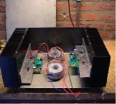
Now I use SK157 (0.25d/W) heatsink, better power supply elco's
(C-L-C configuration).
When it is finished, I will add my listening impressions here.
Best Regards:
Ron

I am new in this forum, but I am building amplifiers for some time now.
I followed this thread for a while, and I am building the JLH also.
I builded the 10 watt version with the following setup:
Power supply: 2x15VDC/300VA
BJT's: BC560C, 2SC3421, BD140, and MJ15003.
I included C4, and added 100nF in parallel on it because of slight oscillation around 14KHz. (introduced by the inductive component of C4).
I didnot use "audio grade" elco's because it was an experiment, but I like it, and rebuild it with better components.
Now I use SK157 (0.25d/W) heatsink, better power supply elco's
(C-L-C configuration).
When it is finished, I will add my listening impressions here.
Best Regards:
Ron
JLH input transistors
I can't help with the BC560/MPSA56 comparison as I have not tried a BC560 on the input, but I have tried BC212/MPSA56/2SA970/2SA872 in this position. Of these, the cleanest and most detailed sound came from the last two (2SA970/2SA872)), with the 2SA970 sounding the warmer of the two. However, the 2SA872 may not have given its best due to an oscillation problem that was made much worse with this transistor.
It is some time since I last heard the BC212 in my JLH but my preference would probably be for this over the MPSA56.
Tim.
jlh input
I had a BC212 at the input and tried the 2sa970 next. I preferred the sound of the bc212 and put it back in place. It is the only deviation from the mod's that Tim A described at the site of Geoff Moss in the latest version of the JLH (march 2003) (all other mods, like changing to MJ15003's and 2SC3421, did work out exactly as he described).
I must say however that the BC212 I use is from ITT and that my 2sa970's are brandless (do not know the manufacturer). The sound of the bc212 in my case was more open and had crisper highs. The 970 sounded more shut-in and had a slightly rolled-off treble.
I use 3 BC560's for the 2 CCS's (and a BD140). This works fine, also in the case where C4 is left out. I did not measure anything, I only listen by ear, but the amplifier is dead quite, works fine for more than 4 months now, sound as the very best version of all JLH's up to date (I built them all from 1969 original, 1996 version, a mix of both versions, and the march 2003 'CCS' version).
Could it be that I miss some oscillation that is there but can't be heard. I am slighty worried because so many people experience some form of oscillation with the newest version and/or faster transistors?
JLH input/oscillation
rmgvs,
In my circuit there were two methods available to me to test for instability (I had no oscilloscope). The first method was to listen with my ear as close as possible to the speaker during switch-on, and for a couple of minutes after switch-on. Any problem was almost always noticeable within these two minutes in the form of intermittent noise (similar to RF interference). Usually a short noise would appear in the first few seconds, followed by a long silence, followed by a slow build-up of noise again. However the noise was usually (but not always) so quiet that the windows had to be shut and the cat prevented from coming near me during listening. With the cat a metre from me, and the speaker to my ear, his paws on the carpet were often louder than the noise I was listening for, the noise was usually that quiet!
The other reliable (in my circuit) method was to adjust VR3 fairly slowly through full travel whilst monitoring the dc offset. The dc offset would move rapidly in one direction (a few hundred mV), then turn and move rapidly in the other direction, all this during rotation of VR3 in one direction only. After fitting MPSA56 devices in both CCS circuits, all noises were gone, and the dc offset moved in one direction only during a single rotation of VR3 (I do mean VR3, not VR1).
Incidentally, after changing from BC212 to 2SA970 I too initially had mixed feelings. However after more prolonged listening I concluded that any doubts I may have had were misplaced and that the smoother sound of this transistor was not only the cause of my initial (false) impression of less clarity, but also of greater refinement. I far as I can tell my 2SA970s are genuine Toshiba, though I am unsure about the source of my BC212s.
Tim.
input 2
Tim,
Thanks for the method of discovering oscillations.
I tried both methods and both have positive (ie: no oscillation) results. I have sensitive speakers (Klipsch) around 94 dB/1 Watt/1 mtr, and no hiss/noise can be heard at all when putting your ears INTO the speaker/tweeter. I can not even detect the difference between on and off in this respect (yes, I hear a slight buzz when turning the amp on in the woofer, this problem is well known, the offset is not within 100 mV immediately). To be 100% sure, I guess one needs an oscilloscope. But if nothing can be heard, the sound is really good, and nothing is destroyed, who cares?
About the 970 and difference in perceived sound. I think there are 3 possible explanations:
1. Different makes can matter. I have experienced this on several occasions. The only thing we know know for sure is that Toshiba 970's and ITT BC212 can sound good in this circuit. If more people report their resuls with differents sorts of input T's alongside the brands/markings, we all learn.
2. It can be a matter of the overall picture and balance. In fact we use different power supplies, different resistor brands, differents lay-outs, different speakers etc. We all know that the wrong input C can destroy the sound, maybe some type of input C corrects the sound of another input T.
3. Of course we do have different ears and tastes. But this is interesting since I repeated all steps of Tim and could confirm all results made by him. I am not a musician as Tim but 'listen' to different caps, transistors etc for more than 10 years now and the result is that I for myself have a rather consistent view on what to achieve soundwise.
Rudy
Nexus said:Hello all,
does anyone knows an adress (preferred in the Netherlands), where I can buy WIMA capacitors?
Greetz.
Stuut en Bruin in The Hague has WIMA MKP10 on stock in various sizes.
Call them and ask them
 here's their website
electrolytics
Now as a sequel to the WIMA question:
where could I buy a sample of different higher quality electolytics for testing them in the signal path? I'm looking for 10 mF/35 V (voltage can be higher of course).
I hear that some grades/brands are really good: Elna, Silmic, Black Gate, Panasonic etc. They all cost nothing (50 Eurocents to 1 Euro a piece). Ordering them abroad is not practical because of the extra costs of shipping etc.
Where can I get (some of) these in the Netherlands?
Rudy
WIMA
dont understand why people always want to have exotic things from overseas.
WIMA is about one hour with car away from me.
(although they dont sell to end.-customers)
We in germany like to tend to american and japanese parts like vishay s102k resistors, auricaps....
i dont think the Wima MKP`s are that good.
Greets,
Ralf
wima
Ralf,
1. WIMA and ERO were the only audiophile grade caps available here around 1980. Since then a lot has changed. The articles of Hiraga did have influence, there was a new market for expensive components and much more is available today.
2. Not all WIMA's are equal. I think some MKS-series are/were really exceptional. Hirage used them in his own tube-preamps. I recently used one of these again and it still is one of the very best around. I never liked the MKP series myself: they were souding too hifi.
3. I even experienced differences in sound between different voltage in the same series of WIMA-caps (630 in stead of 400 V). Even differences between different values of the same series/same voltages. Strange things.
4. Did you know that WIMA produce (..d?) paper-in-oils? They sound very tube-ish (the one I tried) but there misses some detail in the highs. Surely not as good as the Jensen and audio-note caps (but in a different price league however).
Rudy
Re: electrolytics
Hi Rudy,
you're several weeks late: I ordered a lot of stuff from www.schuro.de and could have included these at no extra charge. But try this forum and the forum om www.hifi.nl and post a thread like " is someone ordering these?".
I've got almost all stuff in the house now.
(except two vishay/spectrol trimmers where I made an error in the number I ordered. And ordering the single two will cost a fortune)
rmgvs said:Now as a sequel to the WIMA question:
where could I buy a sample of different higher quality electolytics for testing them in the signal path? I'm looking for 10 mF/35 V (voltage can be higher of course).
I hear that some grades/brands are really good: Elna, Silmic, Black Gate, Panasonic etc. They all cost nothing (50 Eurocents to 1 Euro a piece). Ordering them abroad is not practical because of the extra costs of shipping etc.
Where can I get (some of) these in the Netherlands?
Rudy
Hi Rudy,
you're several weeks late: I ordered a lot of stuff from www.schuro.de and could have included these at no extra charge. But try this forum and the forum om www.hifi.nl and post a thread like " is someone ordering these?".
I've got almost all stuff in the house now.
(except two vishay/spectrol trimmers where I made an error in the number I ordered. And ordering the single two will cost a fortune)
power supply:
2x15V 120VA C-L-C topology.
After building it without C4a, I noticed some oscillations around 14KHz,
cause of this was the inductive component of C4,
100nF was placed in parallel with it, and the oscillations were gone.
further the higher spectrum was checked, and some oscillations were found in the higher regions.
after placing a capacitor of 33pF in parallel with R8, this was solved also.
The spectrum is from 8Hz to 94KHz now (-3dB),
with a good looking sine wave (no distortion meter present to check).
When Q3 is replaced with a BD139, the the extra cap over R8 can be removed and
the spectrum gets much larger, so I will test the sonics of both configurations.
And I will do some test with WIMA input capacitor and elna silmic for C4.
Greetings.
Attachments
- Home
- Amplifiers
- Solid State
- JLH 10 Watt class A amplifier