argo said:chris,
Good work indeed.
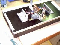
What is that big grey can next to input RCA - an input capasitor?
argo
Yes the grey oil can is a 2.5uf input cap. I don't know whether it will work or not, for I have no alternative caps around for now.
Still trying to source a suitable input cap. But if this one work and sound good, then it will stay.
Chris
Has anyone the voltage over C4 handy?
Hi, has anyone the voltage over C4 available.
Why?
I've found 4 1500uF 6.3V Panasonic FC capacitors in my 'nice-to have capacitor container'. Probably they came of a computer PCB.
As I'm constructing the 2003 ESL version I've no way to take measurements at this moment.
And it might be a good idea to use these iso the 470 uF C4 which I've got planned.
Any comments on this idea?
Re: Has anyone the voltage over C4 handy?
Hi,
Just F.Y.I,
I don't remember who it was on Geoff site that tested diffrent values up to 1000uF and 470uF was found to be optimal.
dutch diy said:Hi, has anyone the voltage over C4 available.
Why?
I've found 4 1500uF 6.3V Panasonic FC capacitors in my 'nice-to have capacitor container'. Probably they came of a computer PCB.
As I'm constructing the 2003 ESL version I've no way to take measurements at this moment.
And it might be a good idea to use these iso the 470 uF C4 which I've got planned.
Any comments on this idea?
Hi,
Just F.Y.I,
I don't remember who it was on Geoff site that tested diffrent values up to 1000uF and 470uF was found to be optimal.
Re: Has anyone the voltage over C4 handy?
If I understand you correctly you are thinking about using a 6.3V cap in the feedback cct. This raises some interesting points.
In both of the JLH versions of this cct he has this cap going to the neg most rail of the amp. this means that there is a voltage of much more than 6.3V across it.
I have noticed that some people have the newer dual rail version of the amp with this C4 connected to earth rather than the neg rail. This would certainly mean that a 6.3V cap should be OK. But the are two reasons why this may not be the best way to go ( if indeed you intend to keep this cap in the cct atall ).
I believe that JLH kept the cap going to the neg rail because he was of the opinion that electrolytics caps work better with a polarising voltage across them which would not be the case if it is run to earth. Also generally speaking the higher the voltage of an electrolytic the better it sounds so using this logic it would be best to go for a higher voltage 470uF going to the neg rail.
Perhaps there are some people that have tried both ways and could shed some light on this.
personally I would try to go for the no C4 option and put up with a highish DC offset. no cap sounds as good as no cap !
My only question would be does DC offset affect the operation of any ferrus cored chokes in the crossover. I'm not sure on this point but I am sure that if these are replaced with air core ones the sound improves considerably !
cheers
mike
p.s. I'm not familiar with this esl version, is there a diagram somewhere to look at ? If the amp is driving a transformer, DC offset could be bad news.
dutch diy said:Hi, has anyone the voltage over C4 available.
Why?
I've found 4 1500uF 6.3V Panasonic FC capacitors in my 'nice-to have capacitor container'. Probably they came of a computer PCB.
And it might be a good idea to use these iso the 470 uF C4 which I've got planned.
Any comments on this idea?
If I understand you correctly you are thinking about using a 6.3V cap in the feedback cct. This raises some interesting points.
In both of the JLH versions of this cct he has this cap going to the neg most rail of the amp. this means that there is a voltage of much more than 6.3V across it.
I have noticed that some people have the newer dual rail version of the amp with this C4 connected to earth rather than the neg rail. This would certainly mean that a 6.3V cap should be OK. But the are two reasons why this may not be the best way to go ( if indeed you intend to keep this cap in the cct atall ).
I believe that JLH kept the cap going to the neg rail because he was of the opinion that electrolytics caps work better with a polarising voltage across them which would not be the case if it is run to earth. Also generally speaking the higher the voltage of an electrolytic the better it sounds so using this logic it would be best to go for a higher voltage 470uF going to the neg rail.
Perhaps there are some people that have tried both ways and could shed some light on this.
personally I would try to go for the no C4 option and put up with a highish DC offset. no cap sounds as good as no cap !
My only question would be does DC offset affect the operation of any ferrus cored chokes in the crossover. I'm not sure on this point but I am sure that if these are replaced with air core ones the sound improves considerably !
cheers
mike
p.s. I'm not familiar with this esl version, is there a diagram somewhere to look at ? If the amp is driving a transformer, DC offset could be bad news.
Re: Re: Has anyone the voltage over C4 handy?
Hello Mike, check this posts by Tim
http://www.diyaudio.com/forums/showthread.php?postid=201384#post201384
Chris
mikelm said:
....not familiar with this esl version, is there a diagram somewhere to look at ? If the amp is driving a transformer, DC offset could be bad news.
Hello Mike, check this posts by Tim
http://www.diyaudio.com/forums/showthread.php?postid=201384#post201384
Chris
re C4 inclusion
Hi Mike,
I've built a dual-mono setup of the 1996 version with the C4 included (to earth).
However I cannot compare it to versions built without C4.
I'm now building the 2003 esl version from the schematic with a C4. One change: a .1uF mkp will be in parallel of a 470uF elna silmic.
As I will build two monoblocks I could decide to build one without C4 / C4a. But I'm not keen on taking one apart after I spot a significant difference in sound quality. As they will be installed in my main system its no option of testing partly assembled amps. Basically my wife does not like that . It's ok to diy but only completed devices can be introduced into the living room.
Jos de Weerdt
Hi Mike,
I've built a dual-mono setup of the 1996 version with the C4 included (to earth).
However I cannot compare it to versions built without C4.
I'm now building the 2003 esl version from the schematic with a C4. One change: a .1uF mkp will be in parallel of a 470uF elna silmic.
As I will build two monoblocks I could decide to build one without C4 / C4a. But I'm not keen on taking one apart after I spot a significant difference in sound quality. As they will be installed in my main system its no option of testing partly assembled amps. Basically my wife does not like that
. It's ok to diy but only completed devices can be introduced into the living room.Jos de Weerdt
First of all, sorry about the typo, it should say "sucess" and not "exit" (exito is the spanish for success... it was late )
I just became aware that Geoff's site will be down for a while. In the meantime, i have most of the site archived (in .txt files and the images), and if it's of any help for everyone, just let me know. Feels like it's the very least i could do.
)I just became aware that Geoff's site will be down for a while. In the meantime, i have most of the site archived (in .txt files and the images), and if it's of any help for everyone, just let me know. Feels like it's the very least i could do.
Re: re C4 inclusion
Just a suggestion, You can install a jumper across C4/C4a, and use the Vr3 & 47uF setting to begin with. you may even use MPSA56 devices. if you decide to use C4 then you keep the jumper open and just readjust vr3. I used this method for testing the two options after the Amps were finished and in the living room.
dutch diy said:Hi Mike,
I've built a dual-mono setup of the 1996 version with the C4 included (to earth).
However I cannot compare it to versions built without C4.
I'm now building the 2003 esl version from the schematic with a C4. One change: a .1uF mkp will be in parallel of a 470uF elna silmic.
As I will build two monoblocks I could decide to build one without C4 / C4a. But I'm not keen on taking one apart after I spot a significant difference in sound quality. As they will be installed in my main system its no option of testing partly assembled amps. Basically my wife does not like that
Jos de Weerdt
Just a suggestion, You can install a jumper across C4/C4a, and use the Vr3 & 47uF setting to begin with. you may even use MPSA56 devices. if you decide to use C4 then you keep the jumper open and just readjust vr3. I used this method for testing the two options after the Amps were finished and in the living room.
Re: Re: re C4 inclusion
Hi Mike,
wonderfull suggestion. Bloody I just sent of my PCB layouts for manufacturing two days ago, without Vr3 and without jumper option. I've got a bunch of 2SA970's but I'll check the datasheet of the MPSA56 for pinlayout later. (I'm on holiday now and this is not my home-pc). The cost of getting those shouldn't be too great I presume and if the have the same pinlayout it isn't a problem to replace them.
But, I'll keep that in mind for a Rev-F of the PCB layout.
Jos
Miki F said:
Just a suggestion, You can install a jumper across C4/C4a, and use the Vr3 & 47uF setting to begin with. you may even use MPSA56 devices. if you decide to use C4 then you keep the jumper open and just readjust vr3. I used this method for testing the two options after the Amps were finished and in the living room.
Hi Mike,
wonderfull suggestion. Bloody
I just sent of my PCB layouts for manufacturing two days ago, without Vr3 and without jumper option. I've got a bunch of 2SA970's but I'll check the datasheet of the MPSA56 for pinlayout later. (I'm on holiday now and this is not my home-pc). The cost of getting those shouldn't be too great I presume and if the have the same pinlayout it isn't a problem to replace them.But, I'll keep that in mind for a Rev-F of the PCB layout.
Jos
C4 inclusion
Jos,
I think that you can do with the PCB as is.
you just have to replace R1 with a trimpot, ok you may need to drill a bit and solder a short to the center tap, but that should not be a problem.
There is one another thing, the original 2k pot is replaced with a 200R when using the Vr3. I Kept the 2k pot which made setting the DC offset a bit annoying but can be done.
why did you choose silmic caps ?
Miki
Re: C4 inclusion
Nothing more.
Wrong choice?
They were available at www.schuro.de at a reasonable price.Miki F said:why did you choose silmic caps ?
Nothing more.
Wrong choice?
- Home
- Amplifiers
- Solid State
- JLH 10 Watt class A amplifier