The PNP BJTs amp sounds better than two amps of NPN BJTs amp.
the BJTs of the PNP amp:
2SA970 2SB649A MJ15025*2
the BJTs of the NPN amp:
2SC2240 2SD669A MJ15003(or 2N3055 or 2SD555)*2
The circuit and the front panel pic will post days later,because of i have not a scanner .
Cheers.
X.G
the BJTs of the PNP amp:
2SA970 2SB649A MJ15025*2
the BJTs of the NPN amp:
2SC2240 2SD669A MJ15003(or 2N3055 or 2SD555)*2
The circuit and the front panel pic will post days later,because of i have not a scanner .
Cheers.
X.G
Ultimate JLH ?
Hi,
I read through the posts for a while now and will build a JLH as well. As it is fairly simply to build, I want to go for an "ultimate" version sort of speak. I learned so far that it should consists of:
- choke-input-suppply, maybe with cap multipl. or completely passive
- Two rect. bridges per channel
- maybe PNP (I am looking forward to the schematic)-Transistors
- Starwired, p2p
- Separate power supplies / stages for Driver and End-Trasistors with same voltage
- Lots of current, at least 2 A through each powertransistor
- Small, high-quality cpacitors like Silmics
- MAtched Transistors all over the place
- No Input cap(my preamp has already an output cap)
Anything else you would suggest ?
By the way: Instead of going to the 2003 ESL-version, wouldn't it be a greater idea to take the setup of the 15W-version and design a bridged version, so some kind of a X-JLH ?
Best REgards
Re: Ultimate JLH ?
Your thinking is great!!!
good luck
Blitz said:Hi,
I read through the posts for a while now and will build a JLH as well. ......
Your thinking is great!!!
good luck
Re: Ultimate JLH ?
Nice choice. Here's my pick-list:
1 My personal believe is in regulated PS. no sonic arguments pro / con.
2 two bridges made of fast, soft recovery diodes are a good thing to have per amp.
3 I just used MJ15003 / 2SC3421 as proposed
4 I made a PCB for amp and PS
5 I used a regulated PS for all: but this is an Idea which might be explored (but can only be made practical with multiple regulated ps's)
6 NOT my idea: less current through multiple devices reduces "load" and "wear" on each device and makes heatsinking less critical. (IMHO extend the 2003 diagram to have 6 MJ15003's in the output stage)
7 I've used one large BC154 and two smaller Panasonic FC to give a total of 51.400uF per rail @ 31.5V unregulated (under load) in the PS. No-brand cap's have been used for the various 100uF caps from rail to ground. I used Panasonic FC for the C5.
8 I've matched output quads and picked all 2SA970 to have hfe within 5%
9 Good idea. I've used a Jensen PIO but I'll check dc voltage across it.
10: A bridged version might be a splendid idea it however needs an additional phase-splitter section.
It probably eliminates the DC-offset drift over temp change.
11: I used a C4 (a Silmic 470uF bridged by a 0.1uF MKP from Wima). But discussion are not closed on removing this cap at all !!
Blitz,Blitz said:Hi,
I read through the posts for a while now and will build a JLH as well. As it is fairly simply to build, I want to go for an "ultimate" version sort of speak. I learned so far that it should consists of:
1 choke-input-suppply, maybe with cap multipl. or completely passive
2 Two rect. bridges per channel
3 maybe PNP (I am looking forward to the schematic)-Transistors
4 Starwired, p2p
5 Separate power supplies / stages for Driver and End-Trasistors with same voltage
6 Lots of current, at least 2 A through each powertransistor
7 Small, high-quality cpacitors like Silmics
8 MAtched Transistors all over the place
9 No Input cap(my preamp has already an output cap)
Anything else you would suggest ?
By the way: Instead of going to the 2003 ESL-version, wouldn't it be a greater idea to take the setup of the 15W-version and design a bridged version, so some kind of a X-JLH ?
Best REgards
Nice choice. Here's my pick-list:
1 My personal believe is in regulated PS. no sonic arguments pro / con.
2 two bridges made of fast, soft recovery diodes are a good thing to have per amp.
3 I just used MJ15003 / 2SC3421 as proposed
4 I made a PCB for amp and PS
5 I used a regulated PS for all: but this is an Idea which might be explored (but can only be made practical with multiple regulated ps's)
6 NOT my idea: less current through multiple devices reduces "load" and "wear" on each device and makes heatsinking less critical. (IMHO extend the 2003 diagram to have 6 MJ15003's in the output stage)
7 I've used one large BC154 and two smaller Panasonic FC to give a total of 51.400uF per rail @ 31.5V unregulated (under load) in the PS. No-brand cap's have been used for the various 100uF caps from rail to ground. I used Panasonic FC for the C5.
8 I've matched output quads and picked all 2SA970 to have hfe within 5%
9 Good idea. I've used a Jensen PIO but I'll check dc voltage across it.
10: A bridged version might be a splendid idea it however needs an additional phase-splitter section.
It probably eliminates the DC-offset drift over temp change.
11: I used a C4 (a Silmic 470uF bridged by a 0.1uF MKP from Wima). But discussion are not closed on removing this cap at all !!
sparkle said:hello guys!
i'm building jlh 15w amplifier with modifications made by mr. moss and I must say that this thread was so much help for me - many opinions and informations- it's good to have forum like that around
daniel
I hope you have a good result.
I just moved my 2003 versions of the JLH to my living room and they are great.....
work in progress
Hi,
I was unit testing one channel of the JLH2003 updated version over the weekend. The PSU has one Piltron 400VAC 22-0-22 using MUR860 full wave bridges to 10@4700uf caps to 3mH air coil to 99000uf of mixed size caps for each power rail. No earth ground connected at the moment, need to find a way. Remote PSU to amp via a seven feet long 10/4 awg 10 cable, all cases are made by MDF boards.
I managed to let the steam out of C7 slowly using a variac. Not using reverse polarity of C7 between ground and negative power rail was the mistake. Set Iq current at 150mv across R13. The MUR860s just get a little warm. DC offset at zero, all power transistors are 2N3055 for testing, loud noise from test speaker, problem found, the big gray oil can input capacitor bought from surplus was acting like a super antenna, make very very loud noise when I touch the cap.
There was no other cap suitable at home but I managed to use five 0.1uf polypropylene as C1, reduced noise, replaced all 2N3055 with MJ21194, faint noise from speaker, connected just the input RCA interconnect without the pre-amp the noise went away, dead quiet, don’t understand why?
will continue....
Regards,
Chris
Re: work in progress
I wonder if you haven't run into the same issue TimA ran into with the 21194. Do you have 15003s to drop in?
eL
chris ma said:Hi,
*snip*
There was no other cap suitable at home but I managed to use five 0.1uf polypropylene as C1, reduced noise, replaced all 2N3055 with MJ21194, faint noise from speaker, connected just the input RCA interconnect without the pre-amp the noise went away, dead quiet, don’t understand why?
will continue....
I wonder if you haven't run into the same issue TimA ran into with the 21194. Do you have 15003s to drop in?
eL
Hi eL,
I am not sure yet, but that's what I will try to find out. The faint noise from the speaker was the same whether I have the MJ21194 or 2N3055 in when there was no interconnect cable plug into the input RCA. But if the interconnect is in there is no noise I can hear with the speaker pressed to my ear. The test speaker is a small one a 5 x 6 x 7 inches in size and 8ohm. The other test I did was to connect the interconnect cable and pressed my finger to the inner pin of the cable to induce hum with the speaker in my hand pressed to my ear for over half an hour tried to listen to any irregularity beside the hum, and I could not hear anything else. The hum is very steady that I like. Once I removed my finger from the interconnect it went dead quiet again.
Should I try to short the input instead to listen for noise?
Regards,
Chris
PS: The MJ15003 will stay with my JLH for ESL. I am not touching that pair of amps
chris ma said:The faint noise from the speaker was the same whether I have the MJ21194 or 2N3055 in when there was no interconnect cable plug into the input RCA. But if the interconnect is in there is no noise I can hear with the speaker pressed to my ear.
Hi chris,
I think because this amp has no compensation it is very easy to end up with some very high frequency oscillation which I would guess is what is happening.
Although there may be other methods of curing this ,in circumstances like this a small cap across the i/p can often make the difference between oscillation or no oscillation.
The lead that you plug in is providing that capacitance. If you put a cap of about 20pF across the i/p it might cure the problem. If not you could try slightly higher values, polystyrene would be best I guess.
hope this helps
mike
8 output tansistors
Hi,
Around last year sometime I did simulate with 8 @ MJ15003 with Simetrix4 for the JLH for ESL. Everything seems fine except the load of the output transistors were sharing the lower load each.
As long as I maintainded the original bias and PSU voltage I don't see why not. No changes I could see happened to the driver transistors part of the circuit. Of course that's just simulation may be different in real live.
Like you said only extra effort and time, oh and cost or those 0R1 resistors are expensive. The new ones that I am using are the ohmite(spell right?) ones that cost more than the caddocks around $12 cdn each from Digitkey.
Chris
parallel output transistors
Hi,
since Q1 and Q2 are driven by a ccs it is perhaps possible to reduce cost (just an idea that have to be simulated): As long as all Q1 and all Q2 have the same base current, you can parallel them.
For every output Pair (Q1 and Q2) use an own current source(Q7 / 8 ) and an own Current Splitter Q3 with his own R9.
Select all Q3 for nearly the same Betta and add on an Emitter Resistor of about 1 Ohm, adjust the quisent current separatly for every output Pair (Q1 and Q2), leave all emitter Resistor for Q1 and Q2. Or in other words : Multiply the cirquit of the 10W version from the base of Q3 to Q1/2 and connect all outputs together.
In this configuration the cost intensive components aren't anymore in the cirquit (you can also leave R10 or replace it with a 0.01 Ohm / 1W version) . The open question: Is there enough Current from Q4 to drive 4 times a Q3 and is the stability still ok.
I don't have a simulation program to check that. What's your comment?
Regards
Daniel
Re: My PNP version
that's nice, John.
Just curious if anyone has actually built a mosfet version of jlh. I simulated a jlh1969 with irf540 as output devices (you have to change some of the values) and it looked very nice on paper but i have no idea how well it will do in reality.
So anyone tried mosfets on those amps?
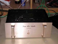
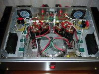
jccliu said:My PNP version completed in a few months ago.
John
that's nice, John.
Just curious if anyone has actually built a mosfet version of jlh. I simulated a jlh1969 with irf540 as output devices (you have to change some of the values) and it looked very nice on paper but i have no idea how well it will do in reality.
So anyone tried mosfets on those amps?
OK, here is the mosfet jlh1969 that I put together.
it uses two irf540 as output devices. No signs of instability in simulation (so no gate stoppers for the IRFs), and A/C hum (for a 10vpp ripple on the supply rail) is 50mvpp.
THD at full power: 0.12% @20Khz, 0.07% at 10Khz, 0.05% @ 1Khz, and 0.05% @ 100hz.
response flat to 100Khz and starts to roll off after 300Khz.
I haven't built one yet and would love to see other's experience with a mosfet jlh.
Attachments
- Home
- Amplifiers
- Solid State
- JLH 10 Watt class A amplifier