If you want to get funky with CCS onkyos patent US4945301
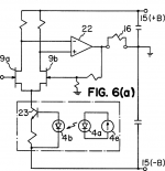
"In operation, the light emitted from the electricphoto conversion element 4a excited by the power source 4e causes the photosensitive element 4b to generate a voltage, & this voltage is applied to the base of the transistor 23 as the reference voltage, whereby a constant current is delivered to the common emitter of the differential amplifier stage FET's 9a & 9b.
Incidentally, it is preferred that the driving power source 4e to be input to the light emitting 4a be picked up from a power supply line portion uninfluenced by the DC power source variations. However, even if this power source 4e is picked up from the DC voltage portion, as long as the light emitting element 4a is capable of supplying a voltage sufficient for an operation within its saturation current range, it is possible for the photosensitive element 4b to generate a constant voltage unaffected by the DC power source variations."
Attachments
Mike,
The diode string drops about 2V over a wide range of VAS currents, good for experimentation.
It reduces the variation on the trimpot, keeping the quiescent adjustment constrained, to avoid accidents.
It is a congenial way to secure some thermal compensation in very hot climates should the amp get VERY hot.
The string is an elegant way of bridging tracks on the pcb.
Cheers,
Hugh
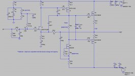
Latest version...sounding very good.
Look carefully, there's more changes than you might think...
For me the jury is still out about the phase lead cap. It improves separation and stability but I think it really kills the foot tapping factor - just my opinion. I think I actually prefer it without.
Lower gate stoppers on VAS and output fets has improved bandwidth to easily several hundred kHz. For these values you will need a very efficient layout if you don't want oscillation on the negative half cycle under no load conditions. Lower gate stoppers has improved musicality.
Enjoy.
Attachments
Look carefully, there's more changes than you might think...
For me the jury is still out about the phase lead cap. It improves separation and stability but I think it really kills the foot tapping factor - just my opinion. I think I actually prefer it without.
Lower gate stoppers on VAS and output fets has improved bandwidth to easily several hundred kHz. For these values you will need a very efficient layout if you don't want oscillation on the negative half cycle under no load conditions. Lower gate stoppers has improved musicality.
Enjoy.
In my experience if you have lead compensation then the miller cap can be reduced to a very small value or possibly omitted. In my setup I have less than 5pF miller which deals with an extreme HF oscillation only and load related stability issues will be dealt with in other ways - if needed - when I was doing my spice research I concluded that in this circuit miller compensation didn't really help anything but I had to add this tiny value when switching to 4424a
I would be interested to hear if you tried lead compensation on it's own recently and if that still had the foot tapping killer effect - my efforts in this area will begin in earnest when my waveform generator arrives.
I'm guessing that the different characteristics of DC & AC feedback will mean that the optimization processes will probably lead to different outcomes.
Andrew, thx for the explanation, I was in a DC linking mindset. Hope your managing to figure it out.
mike
Last edited:
Look carefully, there's more changes than you might think...
For me the jury is still out about the phase lead cap. It improves separation and stability but I think it really kills the foot tapping factor - just my opinion. I think I actually prefer it without.
Enjoy.
Hello
Which minimum phase lead cap value have you try ?
47pF is quite high.
I never use more than 16pF for the phase lead cap, usually I use arround 6 to 10 pF.
And I try to keep my cdom cap value under 20pF.
Both cap value chosed for difficult load speakers.
Thank
Bye
Gaetan
Last edited:
Gaetan
The value of lead caps has to be inversely related to the chosen resistance values in the feedback circuit to give a similar effect so just stating a cap value does not really provide enough info.
An added factor for me is that in the DC version, reducing the FB resistor values also increases OLG so my cap values may have to increase even more in these circumstances.
Gaetan
The value of lead caps has to be inversely related to the chosen resistance values in the feedback circuit to give a similar effect so just stating a cap value does not really provide enough info.
An added factor for me is that in the DC version, reducing the FB resistor values also increases OLG so my cap values may have to increase even more in these circumstances.
Hello
Yes, and I alway use relatively low OLG, arround 60 db (and a close loop gain arround 30 db), so stability are easyer to obtain with low value cap.
Thank
Bye
Gaetan
Last edited:
Some more numbers.
2.8Hz to 94kHz +0-1dB
1.8Hz to 174kHz +0-3dB
My input filters are set to 100ms and 0.68us
~1us delay @ 270kHz
No sign of oscillation @~0.08Vac (~80mVac = 800mVac@ output within passband) input all the way up to 1Mhz sinewave.
Without Cdom, i.e. no compensation.
My gain is ~+19.7dB not 10.8times, due to resistors at the input.
Still to try higher output levels.
Last edited:
")
Did some clipped signal testing late last night.
The -ve clips first and about a volt later the +ve clips.
Both peaks come out of clip cleanly even when grossly overloaded into 50r0 was attempted @ 1kHz.
I got 14.5Vac using +-25Vdc rails and 18.6Vac using +-30.5Vdc just before visible clipping into 50r0. Tried a slightly clipped sinewave from 100Hz to 20kHz to see if there was any difference.
Yes, at 10k to 20kHz just before clipping, I can see some visible distortion on the falling side of the -ve (i.e. as the signal approaches peak -ve voltage) after it passes peak -ve the rising side seems to be normal sinewave. The positive half does not shows this curve distortion. If I turn down the output voltage from 18Vac to 15Vac, the curve looks completely clean. I wonder if the slight curve distortion is one wavelength of a high harmonic?
Any thoughts.
Coming out of clip at highish frequency still shows a clean corner, as the signal falls away from maximum output.
I think I'll pick up a carton of courage and try max & overloaded into 16r and 8r0 soon.
BTW,
I have started assembling second channel of NFetZilla but this time with source resistors. The Pchannel VAS version is simply FetZilla
Last edited:
This design is specifically aimed at driving Lateral output mosFETs.
Toshiba are vertical mosFETs.
If you are capable you can re-design to suit the Toshibas and post your results in a new thread.
BTW,
I am using 1k0//1k0 (600mW+600mW) in the upper leg of the NFB loop.
At -20dB ref maximum output these resistors will be running at <3% of maximum rated dissipation.
Toshiba are vertical mosFETs.
If you are capable you can re-design to suit the Toshibas and post your results in a new thread.
BTW,
I am using 1k0//1k0 (600mW+600mW) in the upper leg of the NFB loop.
At -20dB ref maximum output these resistors will be running at <3% of maximum rated dissipation.
Last edited:
Yes I will do, I have design a hybride, but is not here, I play a long times with audio, but have also to much other things to do.
A dual mu-stage hybride is on the way, this have feedback.
I drawn your design in multisim and see what it does with vertical mosfets, I have use them in the hybride without temp compensation, but will implement it, she sound far better than the 2sk1058 and 2sj162 but this is afcourse personally tast.
Andrew, I'm not quite sure what you mean about clipping distortion showing high order harmonics. But that's really what any trace is, just a bodaciously complex set of harmonics, only it's being seen in the time domain and not in the frequency domain as in an FFT. So essentially everything you see that deviates from the fundamental is some sort of harmonic or interference. The straight line on the top of a square wave is in fact, when understood harmonically, a special set of mixed sine waves which combine in such a way to create a straight line...
- keantoken
- keantoken
Hi Kean,Andrew, I'm not quite sure what you mean about clipping distortion showing high order harmonics. But that's really what any trace is, just a bodaciously complex set of harmonics, only it's being seen in the time domain and not in the frequency domain as in an FFT. So essentially everything you see that deviates from the fundamental is some sort of harmonic or interference. The straight line on the top of a square wave is in fact, when understood harmonically, a special set of mixed sine waves which combine in such a way to create a straight line...
- keantoken
the slight distortion I can see on very high level outputs, but short of clipping is not the start of the third and higher odd harmonics due to clipping.
It appears only on the negative going half of the sinewave. Even though the -ve half clips before the +ve half, I had to reduce the output level by ~ 3 to 4V from peak/clipping level to return to a visually clean sinewave.
- Status
- This old topic is closed. If you want to reopen this topic, contact a moderator using the "Report Post" button.
- Home
- Amplifiers
- Solid State
- JFET input, MOSFET VAS, LATERAL output = Perfect!!