Hey M10,
Check your sim one more time!
You say the throat piece is 68,5mm but your faulty sim is done with 65mm length. Because of this you get the wrong flare and angles.
I found length was 69mm so no big difference.
375(2441, 2482 etc.) was to be a a permantent magnet knockoff of the field-coil WE594. This one has a longer throatpiece with a flare of 160Hz. For some reason the piece was shortened resulting in the higher flare. For some reason the JBL-techs seems unaware of this as they mention the 2441 being 160Hz in their tech-papers.
Hey M10,
Check your sim one more time!
You say the throat piece is 68,5mm but your faulty sim is done with 65mm length. Because of this you get the wrong flare and angles.
I found length was 69mm so no big difference.
375(2441, 2482 etc.) was to be a a permantent magnet knockoff of the field-coil WE594. This one has a longer throatpiece with a flare of 160Hz. For some reason the piece was shortened resulting in the higher flare. For some reason the JBL-techs seems unaware of this as they mention the 2441 being 160Hz in their tech-papers.
You are absolutely right Revintage. I am a bit dissapointed that you didn't find the other mistake
") . The sim calculates the throat angle, not the mouth angle.
. The sim calculates the throat angle, not the mouth angle.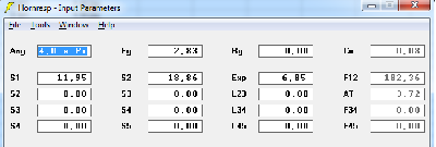
Cutoff is 182 Hz. From the schematic diagram I export the horn data, and it gives the mouth angle. It is 4.67 degrees.
Finally we agree Revintage!
Regarding the difference between JBL and WE, I suspect that JBL simplified (made cheaper) the construction by removing the snout, but kept the mouth diameter. This drawing shows original construction plans:
An externally hosted image should be here but it was not working when we last tested it.

Last edited:
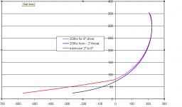
I am proposing to make some adaptors to reduce the throat of my 250Hz Le Cleach horns down from 160mm (for Lowther) down to 52mm for a 2" compression driver. When i used the Le Cleach calculator i have found that the profile does not simply extend backwards. Looking at the spreadsheet it looks as if the natural expansion routine it is using will give a different profile for every throat size. Attached is a graph showing how the profiles differ - what should i do, curve fit a profile "that smooth" from my current throat backwards or ?? suggestions please, as i dont know how sensitive the throat portion of the horn is.
i will be making flanged fibreglass extensions which will bolt on to the back of the existing horns.
VnV,
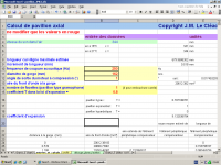
Your adapter problem has been used as a test case for the horn adapter spreadsheet I developed recently. The attached MS/Word file documents dimensions of the adapter that you need. Unfortunately Excel files cannot be attached to messages here; so the formula used have been documented here as well. Comments as well as additions/corrections to this work are welcome.
Regards,
WHG
N.B., due to the product of parameters m * T being fixed by driver exit diameter and flare slope, the required long adapter length and low fc should enhance LF loading of the horn.
Attachments
I have put the data provided into a plot - for comparison. To my uneducated eye it looks a little long, and out of family with Azura and other commercial JMLC horns. My experimentation with conical horns gave long results also.
I have been using curve fitting routines to back predict the existing horn, working out compression instead of expansion. To date all have a point of inflection around 100mm dia where the solution diverges.
I have been using curve fitting routines to back predict the existing horn, working out compression instead of expansion. To date all have a point of inflection around 100mm dia where the solution diverges.
Attachments
Hello,
Often peole speak of a "Le Cléac'h horn profile". The under-meaning of that is that for a given T, a given Fc and various throat diameters the profiles of the obtained horns should share a common profile.
This is not the case, for the obvious reason that for a given distance to mouth, the wavefront shape will not be the same if the throat diameter is a, 2a or na...
So the problem to build an adapter for a Le Cléac'h horn of a given throat diameter in order to use a driver having a very smaller exit diameter is not a trivial one.
In some cases the adding of the adapter will introduce the profile slope twill loose 1st order or second order continuity and this is IMHO a bad thing.
The problem is a bit simpler if the axisymetric horn is calculated for the smaller throat diameter and then cut in order to provide a removable adapter (the wavefront on the membrane of a loudspeaker having a large diameter is lesss well defined also... )
Best regards from Paris, France
Jean-Michel Le Cléac'h
Hello,
Often peole speak of a "Le Cléac'h horn profile". The under-meaning of that is that for a given T, a given Fc and various throat diameters the profiles of the obtained horns should share a common profile.
This is not the case, for the obvious reason that for a given distance to mouth, the wavefront shape will not be the same if the throat diameter is a, 2a or na...
So the problem to build an adapter for a Le Cléac'h horn of a given throat diameter in order to use a driver having a very smaller exit diameter is not a trivial one.
In some cases the adding of the adapter will introduce the profile slope twill loose 1st order or second order continuity and this is IMHO a bad thing.
The problem is a bit simpler if the axisymetric horn is calculated for the smaller throat diameter and then cut in order to provide a removable adapter (the wavefront on the membrane of a loudspeaker having a large diameter is lesss well defined also... )
Best regards from Paris, France
Jean-Michel Le Cléac'h
Hi,
considering your comments here, what are your feelings on the following situation-
A choice between the following-
A JMLC profile 350hz horn with a 1.5" throat (7 degree angle at start of throat) meeting to a 1.5" exit driver with a 0 degree exit angle.
Or a JMLC profile 350hz horn with 2" exit and a 1 inch long adapter to bring the angle down to 0 degrees in order to meet the driver exit angle correctly.
This is a real choice for me as I am looking to buy a 350hz JMLC horn from autotech and meet it with a JBL 2452 driver (0 deg exit angle), but Im concerned about having a 7 or 8 degree 'kink' in the throat.- Would this not render a nice smooth profile pointless to some level?
Regards,
LBS.
Hello lbstyling,
For drivers having an exit angle very different than the throat angle of a calculated hypex adapter, I recommand the use of a quadratic throat adpater.
You may find drawing ( page 8) and formula (page 10 )at:
http://www.excelsior-audio.com/Publications/QTWaveguide/QTWaveguide_WhitePaper.pdf
Best regards from Paris, France
Jean-Michel Le Cléac'h
Hi,
considering your comments here, what are your feelings on the following situation-
A choice between the following-
A JMLC profile 350hz horn with a 1.5" throat (7 degree angle at start of throat) meeting to a 1.5" exit driver with a 0 degree exit angle.
Or a JMLC profile 350hz horn with 2" exit and a 1 inch long adapter to bring the angle down to 0 degrees in order to meet the driver exit angle correctly.
This is a real choice for me as I am looking to buy a 350hz JMLC horn from autotech and meet it with a JBL 2452 driver (0 deg exit angle), but Im concerned about having a 7 or 8 degree 'kink' in the throat.- Would this not render a nice smooth profile pointless to some level?
Regards,
LBS.
Last edited:
Hello,
I wrote previously :
More information can be found in Hughes 's paper :
http://www.excelsior-audio.com/Publ...l & Wavefront Curvature (AES107, 1999-09).pdf
Best regards from Paris, France
Jean-Michel Le Cléac'h
I wrote previously :
For drivers having an exit angle very different than the throat angle of a calculated hypex adapter, I recommand the use of a quadratic throat adpater.
You may find drawing ( page 8) and formula (page 10 )at:
http://www.excelsior-audio.com/Publications/QTWaveguide/QTWaveguide_WhitePaper.pdf
More information can be found in Hughes 's paper :
http://www.excelsior-audio.com/Publ...l & Wavefront Curvature (AES107, 1999-09).pdf
Best regards from Paris, France
Jean-Michel Le Cléac'h
trivial pursuit
This is high school algebra stuff no matter what symbology is used, yours, mine or someone else’s. The wave front area at the throat is represented as the coefficient [St] in Salmon’s formula [Sl = St*(Cosh(m*l)+T*sinh(m*l))^2]; thus, different horn throat size, different horn profile.
Not trivial, but simple still. Two angle-radius pairs, one for the driver, the other for the horn, must be matched while following Salmon’s horn profile. In the horn neck the differences in methods, use of ordinal vs. curvilinear dimensions, is trivial and well within the ‘noise’ of manufacturing tolerances; only in the horn bell, are the differences in dimensioning methodology significant. As one angle-radius pair fix the product of m*T the second sets the ratio between them; thus there is only one adapter solution available when Salmon’s formula is used. So the problem is only, just slightly more complex than trivial. Of course a clothoid segment could be used to make more solutions available.
Here in the horn neck, there is little difference between wave front profile and its span dimensions. What is important is mitigating the diffraction edge created by a mismatch between horn slope and that of a compression driver. For that we may (or may not) sustain a minor change of slope derivatives, which for most cases, will represent an un-measurable difference.
The only way to get a matching horn is by specifying the desired throat radius and slope angle required. This intern fixes the product m*T. That is a mathematical fact of Salmon’s equation irrespective of the coordinate system used to implement it. Note that once [fc] is specified the value of [T] becomes fixed as well.
Regards,
WHG
Hello,
Often peole speak of a "Le Cléac'h horn profile". The under-meaning of that is that for a given T, a given Fc and various throat diameters the profiles of the obtained horns should share a common profile.
This is not the case, for the obvious reason that for a given distance to mouth, the wavefront shape will not be the same if the throat diameter is a, 2a or na...
This is high school algebra stuff no matter what symbology is used, yours, mine or someone else’s. The wave front area at the throat is represented as the coefficient [St] in Salmon’s formula [Sl = St*(Cosh(m*l)+T*sinh(m*l))^2]; thus, different horn throat size, different horn profile.
So the problem to build an adapter for a Le Cléac'h horn of a given throat diameter in order to use a driver having a very smaller exit diameter is not a trivial one.
Not trivial, but simple still. Two angle-radius pairs, one for the driver, the other for the horn, must be matched while following Salmon’s horn profile. In the horn neck the differences in methods, use of ordinal vs. curvilinear dimensions, is trivial and well within the ‘noise’ of manufacturing tolerances; only in the horn bell, are the differences in dimensioning methodology significant. As one angle-radius pair fix the product of m*T the second sets the ratio between them; thus there is only one adapter solution available when Salmon’s formula is used. So the problem is only, just slightly more complex than trivial. Of course a clothoid segment could be used to make more solutions available.
In some cases the adding of the adapter will introduce the profile slope twill loose 1st order or second order continuity and this is IMHO a bad thing.
Here in the horn neck, there is little difference between wave front profile and its span dimensions. What is important is mitigating the diffraction edge created by a mismatch between horn slope and that of a compression driver. For that we may (or may not) sustain a minor change of slope derivatives, which for most cases, will represent an un-measurable difference.
The problem is a bit simpler if the axis metric horn is calculated for the smaller throat diameter and then cut in order to provide a removable adapter (the wavefront on the membrane of a loudspeaker having a large diameter is lesss well defined also... )
Best regards from Paris, France
Jean-Michel Le Cléac'h
The only way to get a matching horn is by specifying the desired throat radius and slope angle required. This intern fixes the product m*T. That is a mathematical fact of Salmon’s equation irrespective of the coordinate system used to implement it. Note that once [fc] is specified the value of [T] becomes fixed as well.
Regards,
WHG
Last edited:
This is a real choice for me as I am looking to buy a 350hz JMLC horn from autotech and meet it with a JBL 2452 driver (0 deg exit angle), but Im concerned about having a 7 or 8 degree 'kink' in the throat.- Would this not render a nice smooth profile pointless to some level?
I've been working on a LC horn for a JBL 2435 for what seems forever now. I'm down to just needing some more filler and then paint. Anyway, what I did when I was designing it was measure the expansion rate through the phase plug of the driver from the slots at the diaphragm to the exit of the driver and try to match that rate to the rate at the start of the horn. Almost all compression drivers have this sharp transition buried inside them where they transition from the phase plug to the throat. You just don't see it because they have that smooth throat section built into the driver. The newer JBL drivers cut off that throat section and leave it to you to include it in the horn.
JBL New vs. Old
Hi JS,
The new phase plug, as incorporated into the JBL 2435 compression driver, is designed to issue plane waves at the throat exit. At this juncture, a slope of the adjoining outer passage wall is 0 degrees. From there-on, curvature and slope in the horn neck should expand as dictated by an appropriately selected [Fc] as well as the aspect ratio to be implemented in the horn bell. This design tack minimizes the severity of the discontinuity occurring at the confluence of phase plug annular channels found in earlier designs by BNL.
Regards,
WHG
I've been working on a LC horn for a JBL 2435 for what seems forever now. I'm down to just needing some more filler and then paint. Anyway, what I did when I was designing it was measure the expansion rate through the phase plug of the driver from the slots at the diaphragm to the exit of the driver and try to match that rate to the rate at the start of the horn. Almost all compression drivers have this sharp transition buried inside them where they transition from the phase plug to the throat. You just don't see it because they have that smooth throat section built into the driver. The newer JBL drivers cut off that throat section and leave it to you to include it in the horn.
Hi JS,
The new phase plug, as incorporated into the JBL 2435 compression driver, is designed to issue plane waves at the throat exit. At this juncture, a slope of the adjoining outer passage wall is 0 degrees. From there-on, curvature and slope in the horn neck should expand as dictated by an appropriately selected [Fc] as well as the aspect ratio to be implemented in the horn bell. This design tack minimizes the severity of the discontinuity occurring at the confluence of phase plug annular channels found in earlier designs by BNL.
Regards,
WHG
Last edited:
Adapter Dimensions
See the attached MS/word File.
Check Input Data (in blue) and let me know if you require changes.
Regards,
WHG
The 250hz horns i currently have which i want to add extensions to were designed with the following inputs.
See the attached MS/word File.
Check Input Data (in blue) and let me know if you require changes.
Regards,
WHG
Attachments
Jean-Michel,
Do you have any insight on how much difference between the OS throat vs Quatratic throat differ in performance?
Do you have any insight on how much difference between the OS throat vs Quatratic throat differ in performance?
Hello lbstyling,
For drivers having an exit angle very different than the throat angle of a calculated hypex adapter, I recommand the use of a quadratic throat adpater.
You may find drawing ( page 8) and formula (page 10 )at:
http://www.excelsior-audio.com/Publications/QTWaveguide/QTWaveguide_WhitePaper.pdf
Best regards from Paris, France
Jean-Michel Le Cléac'h
Hello Soongsc,
There is so few geometrical difference between an OS throat and a quadratic throat that I believe there is no audible difference between them.
Used only at the trhoat of a Le Cléac'h horn, both facilitate to define a more precise wavefront shape at the throat of the horn. We can imagine a common horn (having given Fc and T) and several quadratic or OS adapters for every driver know by their exit diameter + exit angle .
Best regards from Paris, France
Jean-Michel Le Cléac'h
Jean-Michel,
Do you have any insight on how much difference between the OS throat vs Quatratic throat differ in performance?
There is so few geometrical difference between an OS throat and a quadratic throat that I believe there is no audible difference between them.
Used only at the trhoat of a Le Cléac'h horn, both facilitate to define a more precise wavefront shape at the throat of the horn. We can imagine a common horn (having given Fc and T) and several quadratic or OS adapters for every driver know by their exit diameter + exit angle .
Best regards from Paris, France
Jean-Michel Le Cléac'h
Hello,
Hello,
On my main audio system, I listen to my horns in the nearfield (2meters to 3meters), better 3D imaging and less room signature. But this means you have to obtain the best pulse response at the listening place (low distortion crossover,... drivers aligning...)
For sure the sweet spot is for a single person only and this is for an egotist listening, for a larger audience I use a second audio system with different loudspeakers.
Best regards from Paris, France
Jean-Michel Le Cléac'h
just interested from what distance aceptible to listen e-jmlc horns
Hello,
On my main audio system, I listen to my horns in the nearfield (2meters to 3meters), better 3D imaging and less room signature. But this means you have to obtain the best pulse response at the listening place (low distortion crossover,... drivers aligning...)
For sure the sweet spot is for a single person only and this is for an egotist listening, for a larger audience I use a second audio system with different loudspeakers.
Best regards from Paris, France
Jean-Michel Le Cléac'h
Thanx so from 2-meters its okHello,
Hello,
On my main audio system, I listen to my horns in the nearfield (2meters to 3meters), better 3D imaging and less room signature. But this means you have to obtain the best pulse response at the listening place (low distortion crossover,... drivers aligning...)
For sure the sweet spot is for a single person only and this is for an egotist listening, for a larger audience I use a second audio system with different loudspeakers.
Best regards from Paris, France
Jean-Michel Le Cléac'h
So the other simple question i plan to use both of horns
in my 4-way system
so the coveredge must be a liitle better on the hights
if so will be the sweet spot more wide? ^_^
Thanx so from 2-meters its ok
So the other simple question i plan to use both of horns
in my 4-way system
so the coveredge must be a liitle better on the hights
if so will be the sweet spot more wide? ^_^
Hello,
My previous answer concerned the axisymetrical horns I use in my audio system. The e-jmlc horns are controlled horizontal directivity horns and the optimal listening zone is far larger than with the axisymetrical horns. But anyway, you can listen to the e-jmlc in nearfield if you want.
Many horns having large reflections from mouth to throat and having concentrated diffractions sound bad when listened in nearfield. The Le Cléac'h horns are all designed for low reflection from mouth to throat and low diffraction, so they can be listened in nearfield.
Best regards from Paris, France
Jean-Michel Le Cléac'h
- Home
- Loudspeakers
- Multi-Way
- Jean Michel on LeCleac'h horns