BEM/JHS
David,
Have a look at this from John Sheerin’s Website
LeCleac'h horn vs Conical Horn
Regards,
Bill
Hi Bill,
It would be interesting to be able to carry out BEM analyses of the three different profiles, to establish if in fact there are any perceptible differences in the magnitudes of the predicted throat impedance ripples.
I guess one advantage of the latest profile is that the overall horn size is a little smaller....
Noted thanks.
Kind regards,
David
David,
Have a look at this from John Sheerin’s Website
LeCleac'h horn vs Conical Horn
Regards,
Bill
Attachments
That's was done in some studio UREI loudspeakers.especially as the horn begins to widen out and the pressure drops. Maybe something like a more dense open cell foam.
jamikl
http://forums.klipsch.com/forums/storage/6/629610/urei%20815.jpg
Don't remember the result was so good, as those speakers where very colorated, lack of coherency between bass and hight medium.
But, bad horn, bad size proportions between the two loudspeakers and no measurements published means nothing we can conclude about.
I think silicon can be interesting as it is easy to mold, very precise, hight density, not resonant , very difficult to deform with pressure and has some kind of "form memory"... It can be used as the horn form we can solidify from outside with any plaster material, like our ears, with his cartilages + skin..
Last edited:
Horn Errata
I hope now, all errors in previous submissions have been corrected here.
Regards to all,
WHG
Subject: Parameter Relationships for
Le Cleach's Implementation of Salmon's Horn Family
William H. Geiger, 23-Jul-2011,
Updated 1-Aug-2011, Revised 25-Aug-2011
Throat tangent angle [Art] (radians) is determined by Salmon’s shape factor [T]. If T = 0 so is Art = 0 as well, because the horn profile is catinodial with the throat aperture at its apex where the tangent, tan(Art)=0 Here the throat area, Srt = pi()*Rot^2 [1] is calculated using the ordinal throat radius [Rot] only. This area represents the surface of the plan wave entering the horn and remains a flat disk center element of constant area for all subsequent horn segments. The wave front area for subsequent segments is determined by the formula:
Srl = Srt*cosh(m*Ls)^2 [2]
= pi()*(Rot*cosh(m*Ls))^2 [3]
When T > 0 and Art > 0 as well, the horn profile is either hyperbolic (0<T<1), exponential (T=1) or Bessel (1<T<oo).
Now the throat area Srt = pi()*(Rot^2)/Cos(Art/2)^2 [4] represents the area of a spherical wave entering the horn throat. The resulting spherical cap center element continues to expand in area for all subsequent horn segments. (See Attached Drawing) The wave front area of subsequent segments is determined by a far different formula:
Srl = Srt*(cosh(m*Ls)+T*sinh(m*Ls))^2 [5]
= pi()*(Rot*(cosh(m*Ls)+T*sinh(m*Ls))/cos(Art/2))^2 [6]
Note that there are only three degrees of freedom when specifying a horn profile. Here, [Fc], [T], [Art], [Rot] are the interdependent variables that may be specified.
You may set the values of three of them, but not all four.
From the three given the fourth (dependant variable) must be calculated.
The following derivative of Salmon’s formula relates all four.
From [6] above the equivalent radius is
Sqrt(Srl/pi()) = Rot*(cosh(m*Ls)+T*sinh(m*Ls))/cos(Art/2) [7]
And the derivative of [7] is
Tan(Art) = m*T*Rot*(cosh(m*ls) + sinh(m*Ls))/cos(Art/2) [8]
When segment ordinal position Ls = 0 at the throat, then
Tan(Art) = m*T*Rot/Cos(Art/2) [9]
Rearranging [9] the product
m*T*Rot =Tan(Art)*Cos(Art/2) [10]
where
Flare Coefficient (Scale Factor) m = 2*pi()*Fc/c [11]
and
Fc - Cut Off Frequency (Hz)
c - Velocity of Sound In Free Air
(@ 20 ºC & 50% RH, c= 34399 cm/sec)
Attachments
Thanks Bill.
Interesting stuff from John, as always.
Kind regards,
David
Note that there are only three degrees of freedom when specifying a horn profile. Here, [Fc], [T], [Art], [Rot] are the interdependent variables that may be specified.
You may set the values of three of them, but not all four.
Very informative WHG!
The conclusion is that if you want a perfect adaptation to a driver, the exit angle of the driver beeing equal to the entry angle of the horn, you must choose between [T] or [Fc], or find a driver with an exit angle that matches our horn.
Somewhere in the thread Jmmlc says that you can do a spline adaptation between the driver and the horn. I would like a solution with some more equations
.I believe that one can construct a horn with variable [Fs] (or variable [T]) in order to make the adaptation to the throat. If the adaptation is too short I guess there will be diffraction. Is there a rule of thumb for avoiding diffraction? Can it be calculated?
Horn Notes
Presently there is not an analytic solution for Le Cleach’s horn profile beyond what has been presented for the throat aperture. It is apparent that this profile approximates a cornu spiral [1]. I plan to investigate this alternative when time permits. In its present form, Le Cleach’s method accurately reflects real-world wave front geometry and provides a horn mouth that mitigates reflectance and diffraction.
If you start the horn at a [Rot] less than that of the driver then you can truncate the horn profile to get the desired [Rot]. With this tack you will still have to vary [T] and/or [Fc] as well to get the correct [Art].
Use a spline to approximate the entire horn profile after the coordinate points have been calculated. Avoid kluges in the high pressure horn neck. Instead just design the entire horn to match requirements.
To minimize chaos in wave propagation within a horn,
1) Keep overall horn dimensions comparable to the wave length of the lowest frequency [fl] to be passed:
a. Length >= c/(4*fl)
b. Mouth perimeter >= c/fl
2) Keep all passage changes acoustically smooth and gradual:
a. Radius of curvature >= c/(8*fl) (difficult, so just)
b. Avoid sharp edges
Reference:
[1] Cornu Spiral -- from Wolfram MathWorld
Regards,
WHG
Last edited:
The conclusion is that if you want a perfect adaptation to a driver, the exit angle of the driver beeing equal to the entry angle of the horn, you must choose between [T] or [Fc], or find a driver with an exit angle that matches our horn.
Hi more10,
The Hornresp Horn Segment Wizard can help with this process.
Kind regards,
David
Attachments
Last edited:
When T > 0 and Art > 0 as well, the horn profile is either hyperbolic (0<T<1), exponential (T=1) or Bessel (1<T<oo).
Hi Bill,
I thought that a Salmon's family hyperbolic-exponential horn having a value of T greater than 1 and less than infinity was considered to be a Hyperbolic Sine (Sinh) horn, rather than a Bessel horn, and that a Bessel horn was defined by the general expression S = S1 * x ^ m, so that:
When m = 0 the Bessel horn became a cylindrical horn.
When m = 1 the Bessel horn became a parabolic horn.
When m = 2 the Bessel horn became a conical horn.
When m = infinity the Bessel horn became an exponential horn.
Is this not the case?
Kind regards,
David
Last edited:
Yes!
Hi David,
Somewhere, a long time ago, I came across the characterization of Bessel for 1<T<oo (T=oo, conical). I think it was Olson but I am not sure. Of course when T>1, the value of sinh(m*Ls) becomes dominate and derivative (slope) approaches a constant as T -> oo. In the context of musical instrument design there is a quite different and less obscure horn profile also referred to as Bessel that approximates the flare of some of the wind instrument bells. (This is the one you documented here.) This flare is used to trap acoustic energy within the horn at selected frequencies corresponding to the notes of a musical scale.
Regards,
Bill
Hi Bill,
I thought that a Salmon's family hyperbolic-exponential horn having a value of T greater than 1 and less than infinity was considered to be a Hyperbolic Sine (Sinh) horn, rather than a Bessel horn, and that a Bessel horn was defined by the general expression S = S1 * x ^ m, so that:
When m = 0 the Bessel horn became a cylindrical horn.
When m = 1 the Bessel horn became a parabolic horn.
When m = 2 the Bessel horn became a conical horn.
When m = infinity the Bessel horn became an exponential horn.
Is this not the case?
Kind regards,
David
Hi David,
Somewhere, a long time ago, I came across the characterization of Bessel for 1<T<oo (T=oo, conical). I think it was Olson but I am not sure. Of course when T>1, the value of sinh(m*Ls) becomes dominate and derivative (slope) approaches a constant as T -> oo. In the context of musical instrument design there is a quite different and less obscure horn profile also referred to as Bessel that approximates the flare of some of the wind instrument bells. (This is the one you documented here.) This flare is used to trap acoustic energy within the horn at selected frequencies corresponding to the notes of a musical scale.
Regards,
Bill
Thanks Bill - now I understand
.Kind regards,
David
Hello Esperado,
As said by Earl Geddes about HOMs production :
http://www.diyaudio.com/forums/multi-way/103872-geddes-waveguides-534.html
HOM production occurs vhen the tangent angle to the wall of the horn rapidly changes (vs. the wavelength).
Earl Geddes: "The sharper the discontinuity, in terms of rate of change of slope, the more energy there will be in this HOM."
In an OS waveguide most of the "rate of change of slope" is at the throat (in the "quasi quadratic" part of the profile. In a Le Cléac'h the rate of change of the slope is very low at the throat.
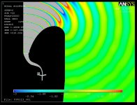
See a comparison of both first derivative and second derivative of a Le Cleac'h horn and an Oblate Spheroidal waveguide here attached.
Now about the frequency dependance : in a Le Cleac'h horn the high frequency front waves "take off" in the first half part of the axial horn length in a zone where there is very few "rate of change of slope"
In conclusion I have to say that one of the main purpose of the Le Cléac'h is to provide very low diffraction and therefore very few HOMs. So, "NO THANKS", we don't need any foam inside a Le Cléac'h horn...
Best regards from Paris France
Jean-Michel Le Cléac'h
As said by Earl Geddes about HOMs production :
http://www.diyaudio.com/forums/multi-way/103872-geddes-waveguides-534.html
HOM production occurs vhen the tangent angle to the wall of the horn rapidly changes (vs. the wavelength).
Earl Geddes: "The sharper the discontinuity, in terms of rate of change of slope, the more energy there will be in this HOM."
In an OS waveguide most of the "rate of change of slope" is at the throat (in the "quasi quadratic" part of the profile. In a Le Cléac'h the rate of change of the slope is very low at the throat.
See a comparison of both first derivative and second derivative of a Le Cleac'h horn and an Oblate Spheroidal waveguide here attached.
Now about the frequency dependance : in a Le Cleac'h horn the high frequency front waves "take off" in the first half part of the axial horn length in a zone where there is very few "rate of change of slope"
In conclusion I have to say that one of the main purpose of the Le Cléac'h is to provide very low diffraction and therefore very few HOMs. So, "NO THANKS", we don't need any foam inside a Le Cléac'h horn...
Best regards from Paris France
Jean-Michel Le Cléac'h
The first ones about HOMs.
Some people adds foam in their " wave guides " ,. Well, i suppose the idea is that lateral waves will across the foam several time, and it will damp them more than the in-axes ones. (My second question can look stupid, somewhere i lie on the way the nature respond to problems. Just i noticed than our 'ears horns' are not rigid. Did somebody had tried to build a horn in silicones ? And, if yes, what about the results ? Can-it solve some of the HOM's problems
Attachments
Last edited:
Hi, Jean-Michel,I have to say that one of the main purpose of the Le Cléac'h is to provide very low diffraction and therefore very few HOMs. So, "NO THANKS", we don't need any foam inside a Le Cléac'h horn...
I don't need to be convinced, as, in the same time you began to work on that subject, we don't knew you at this time, we where talking about similar research with françois Delamare at "La maison du haut parleur" (Tu connais ce pavillon j'imagine ;-) .
His first design was very similar to your. At the end, he achieved a slighty different design, used for the first AERIA system with a different formula based on spheric waves calculations witch, at the end, measures sound and look not so different than your.
I don't agree, along with you, with Earl Geddes's design (pas plus qu'avec sa façon de communiquer ;-) , neither i was convinced by the sound of any 'constant directivity waves guides' on any studio monitors i had worked with, comparing to my 'Delamare' horn. And the use of this kind of chimio therapy damping method (to kill half of the direct energy in order to kill more the HoMs) is nothing i can agree with. I just wonder about the validity of his calculations when adding a damping material witch change a linear pressure to a near adiabatic one. I would never empty my horn with such a material ;-)
But my principal question was about this silicones idea.
I wonder if some silicon skin would be able to damp some residual resonances dues to the less than perfect wave curves out of the phase plug of motors. Did somebody tried-it ?
I don't think it would change a lot the general comportment: Silicones are hard to compress (at the end it is just some 4X the pressure), have a form memory, can have a very precise finish, and it would be an economical way to mold a horn.
I am thinking to a light horn in silicones easy to transport, and that you can fill with rigid material, like concrete or plater, once received. I'm pissed of by the price of (nice looking) wood horns, while an industrialized molded one should be so few $ !
Best regards from "Sud ouest", France ;-)
Last edited:
Horn Quest Notes
Jmmlc,
Some thoughts on horn design come to mind:
1) Assuming good phase plug design, if the surfaces adjoining wave movement are polished there will be less chaos generated there and beyond. I suspect any loss of rigidity (compliance introduced) in horn walls will be detrimental to the loudspeaker mission.
2) There are very few horn profiles that are complete and address the entire impedance transformation problem from enclosed driver diaphragm to the open air. Most are mouthless or such is added as an after thought.
3) In my view, there is little difference between the resulting directivity pattern and this transformation process. One is nothing more than a manifestation other. They are not concepts in opposition that must be sacrificed one for the other.
4) Persuit of 1-P solutions to the horn problem is a like a dog that does not hunt well for its owner.
5) BTW:
Alpha = ?
X_curv = ?
Regards,
WHG
Hello Esperado,
As said by Earl Geddes about HOMs production :
http://www.diyaudio.com/forums/multi-way/103872-geddes-waveguides-534.html
HOM production occurs vhen the tangent angle to the wall of the horn rapidly changes (vs. the wavelength).
Earl Geddes: "The sharper the discontinuity, in terms of rate of change of slope, the more energy there will be in this HOM."
In an OS waveguide most of the "rate of change of slope" is at the throat (in the "quasi quadratic" part of the profile. In a Le Cléac'h the rate of change of the slope is very low at the throat.
See a comparison of both first derivative and second derivative of a Le Cleac'h horn and an Oblate Spheroidal waveguide here attached.
Now about the frequency dependance : in a Le Cleac'h horn the high frequency front waves "take off" in the first half part of the axial horn length in a zone where there is very few "rate of change of slope"
In conclusion I have to say that one of the main purpose of the Le Cléac'h is to provide very low diffraction and therefore very few HOMs. So, "NO THANKS", we don't need any foam inside a Le Cléac'h horn...
Best regards from Paris France
Jean-Michel Le Cléac'h
Jmmlc,
Some thoughts on horn design come to mind:
1) Assuming good phase plug design, if the surfaces adjoining wave movement are polished there will be less chaos generated there and beyond. I suspect any loss of rigidity (compliance introduced) in horn walls will be detrimental to the loudspeaker mission.
2) There are very few horn profiles that are complete and address the entire impedance transformation problem from enclosed driver diaphragm to the open air. Most are mouthless or such is added as an after thought.
3) In my view, there is little difference between the resulting directivity pattern and this transformation process. One is nothing more than a manifestation other. They are not concepts in opposition that must be sacrificed one for the other.
4) Persuit of 1-P solutions to the horn problem is a like a dog that does not hunt well for its owner.
5) BTW:
Alpha = ?
X_curv = ?
Regards,
WHG
Hello William,
4) 1-P solutions have proven to be sufficient to give an accurate estimation of the throat impedance. (comparison with accurate BEM analysis have proven this on the Le CLéac'h horn, thanks Björn Kolbrek.). I consider that the acoustic load seen by the driver is a very important parameter. A resistive and constant acoustic impedance provide a better operation of the driver.
The smoothness of the pressure field is a very important parameter. Non 1-P methods are unable (for the moment) to provide a smooth pressure field inside the horn or the waveguide (... and outside despite some claims).
Remark : I am not against non 1-P solutions, simply no horn or waveguide design based on such solutions ever gave satisfaction to my ears.
Directivity control have probably less importance to those european ears than to american ears ... (that's probably an answer to point 3...)... BUT as it is important to some audiophiles (and even friends of mine) I designed the Iwata_JMLC, the e-JMLC and few others horns which adress (partly) that problem.
5) :
Alpha = the tangential angle of the profile (vs. the axis of the horn)
X_curv = the curvilinear distance to the throat measured along the profile.
Best regards from Paris, France
Jean-Michel Le Cléac'h
Horn Bizarre
4) A defense of the 1-P assumption is raised here, even though validity is known to vanish before the mouth of the subject horn profile is reached [1]. Salmon's horn family is based on a plane wave assumption as well. So applying it to a curvilinear wave front without a recast of internals is questionable. Even though this tack seems to work, I suspect that contour optimality is yet to be achieved. Shape optimization work carried out BÄangtsson, Noreland, Berggren [2], and others, would seem to confirm this observation.
5) "= ?" requests a formula, not a definition of what is already known.
Regards,
WHG
Reference [1]
Title: Methods of Theoretical Physics
Author: Phillip Morse
Subject: Range over which Webster’s equation is effective:
|d sqrt(S0*e^(m*x))/dx| << 1.0
where [S0] is the throat area
[m] is the flare rate
[x] is the length ordinal
Reference [2]
Title: Gradient‐based Shape Optimization of an Acoustic Horn (Contributed Paper)
Publication: J. Acoust. Soc. Am. Volume 119, Issue 5, pp. 3216-3216 (2006); (1 page)
Authors: Daniel Noreland (1), Erik Bangtsson (2), and Martin Berggren (2)
Affiliations: (1) Laboratoire de Mecanique et d'Acoustique, 31 chemin Joseph Aiguier, 13402 Marseille Cedex 20, France
(2) 2Uppsala Univ., 751 05 Uppsala, Sweden
Abstract
Numerical shape optimization is employed in order to improve the transmission properties of an acoustic horn. Wave propagation in the horn is modeled by the Helmholtz equation, which is solved using a finite element method. The shape is modified by changing the position of the mesh points along the contour of the horn. The optimization uses a quasi‐Newton algorithm, with the gradient of the cost function computed by solving the adjoint equation for the discretized forward problem. Key points are the mesh movement scheme and different procedures in order to enforce smooth design updates for a large number of degrees of freedom. Convergence is fast, and the resulting horns have good transmission properties over a wide frequency band.
Hello William,
4) 1-P solutions have proven to be sufficient to give an accurate estimation of the throat impedance. (comparison with accurate BEM analysis have proven this on the Le CLéac'h horn, thanks Björn Kolbrek.). I consider that the acoustic load seen by the driver is a very important parameter. A resistive and constant acoustic impedance provide a better operation of the driver.
The smoothness of the pressure field is a very important parameter. Non 1-P methods are unable (for the moment) to provide a smooth pressure field inside the horn or the waveguide (... and outside despite some claims).
Remark : I am not against non 1-P solutions, simply no horn or waveguide design based on such solutions ever gave satisfaction to my ears.
Directivity control have probably less importance to those european ears than to american ears ... (that's probably an answer to point 3...)... BUT as it is important to some audiophiles (and even friends of mine) I designed the Iwata_JMLC, the e-JMLC and few others horns which adress (partly) that problem.
5) :
Alpha = the tangential angle of the profile (vs. the axis of the horn)
X_curv = the curvilinear distance to the throat measured along the profile.
Best regards from Paris, France
Jean-Michel Le Cléac'h
4) A defense of the 1-P assumption is raised here, even though validity is known to vanish before the mouth of the subject horn profile is reached [1]. Salmon's horn family is based on a plane wave assumption as well. So applying it to a curvilinear wave front without a recast of internals is questionable. Even though this tack seems to work, I suspect that contour optimality is yet to be achieved. Shape optimization work carried out BÄangtsson, Noreland, Berggren [2], and others, would seem to confirm this observation.
5) "= ?" requests a formula, not a definition of what is already known.
Regards,
WHG
Reference [1]
Title: Methods of Theoretical Physics
Author: Phillip Morse
Subject: Range over which Webster’s equation is effective:
|d sqrt(S0*e^(m*x))/dx| << 1.0
where [S0] is the throat area
[m] is the flare rate
[x] is the length ordinal
Reference [2]
Title: Gradient‐based Shape Optimization of an Acoustic Horn (Contributed Paper)
Publication: J. Acoust. Soc. Am. Volume 119, Issue 5, pp. 3216-3216 (2006); (1 page)
Authors: Daniel Noreland (1), Erik Bangtsson (2), and Martin Berggren (2)
Affiliations: (1) Laboratoire de Mecanique et d'Acoustique, 31 chemin Joseph Aiguier, 13402 Marseille Cedex 20, France
(2) 2Uppsala Univ., 751 05 Uppsala, Sweden
Abstract
Numerical shape optimization is employed in order to improve the transmission properties of an acoustic horn. Wave propagation in the horn is modeled by the Helmholtz equation, which is solved using a finite element method. The shape is modified by changing the position of the mesh points along the contour of the horn. The optimization uses a quasi‐Newton algorithm, with the gradient of the cost function computed by solving the adjoint equation for the discretized forward problem. Key points are the mesh movement scheme and different procedures in order to enforce smooth design updates for a large number of degrees of freedom. Convergence is fast, and the resulting horns have good transmission properties over a wide frequency band.
Hello William,
1-P solutions as those given by Webster are non exact solutions, everybody knows that. But most of the formulas used by engineers are such and this doesn't lead to any psychological problem for me... (when it seems to induces physiological tremors to others...)
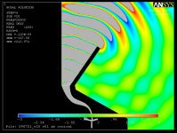
Modelisation methods (BEM, FEM...) demonstrate that the 1-P hypothesis is quasi verified in the Le Cléac'h horn over many octaves above the acoustical cut-off. At HF, both the source directivity and HOMs lead to a directivity monotically varying with frequency (while keeping the pressure field very smooth and with a single lobe of radiation unlike with conical horns and other waveguides inside which HOMs lead to a very complex radiation pattern...).
BTW : the hypothesis of such thing as a plane wave extending over a full section orhogonal to the axis of the horn (as illustrated in many papers and specially for Salmon's horn) is simply ridiculous. That's funny that people like you or Geddes still use that pityfull argument, see first figure in
http://www.gedlee.com/downloads/Horn Theory reply.pdf
As for many differential equations I use in my work (fluid mechanics, rocks mechanics...) the 1-P hypothesis only applies to infinitesimal volume (like the elements you redrawn yourself when you studied the calculation of the Le Cléac'h horn
diyAudio
, all those elements are 1-P except the outer elements noted Ar1, Ar2....
But, that's your part, your are a researcher in audio, not me. I don't need myself to justify my ideas nor to rely on any theorical work to bring some proof that the Le Cléac'h horn provide a constant and resistive load to the driver. Modelisation tools prove it (FEM, BEM...). Also it can be proved using those methods that the Le Cleac'h horn provide the smallest reflectance and diffraction, the smoothest pressure field...
about 5) : I would not offend you in giving formula for the tangential angle to the profile and to the curvilinear distance to the throat...
.
About the design methods (EGO...) used by the industry for the optimization of horns using step by step modification of the profile of a horn as the one you gave in reference. (I gave a similar reference page 110 in my conference on horns given at ETF2010 ) :
Those methods are very interesting, BUT, all of them (to my knowledge) have the same weak initial condition: the 2 ends of the profile are first defined, this induces a severe limitation of the possible shape of the horn at the mouth (no roll back can be obtained). It is interesting though to notice that's the profile of the obtained horn tend to have many analogies with the profile of a Le Cleac'h horn.
Best regards from Paris, France
Jean-Michel Le Cléac'h
1-P solutions as those given by Webster are non exact solutions, everybody knows that. But most of the formulas used by engineers are such and this doesn't lead to any psychological problem for me... (when it seems to induces physiological tremors to others...)
Modelisation methods (BEM, FEM...) demonstrate that the 1-P hypothesis is quasi verified in the Le Cléac'h horn over many octaves above the acoustical cut-off. At HF, both the source directivity and HOMs lead to a directivity monotically varying with frequency (while keeping the pressure field very smooth and with a single lobe of radiation unlike with conical horns and other waveguides inside which HOMs lead to a very complex radiation pattern...).
BTW : the hypothesis of such thing as a plane wave extending over a full section orhogonal to the axis of the horn (as illustrated in many papers and specially for Salmon's horn) is simply ridiculous. That's funny that people like you or Geddes still use that pityfull argument, see first figure in
http://www.gedlee.com/downloads/Horn Theory reply.pdf
As for many differential equations I use in my work (fluid mechanics, rocks mechanics...) the 1-P hypothesis only applies to infinitesimal volume (like the elements you redrawn yourself when you studied the calculation of the Le Cléac'h horn
diyAudio
, all those elements are 1-P except the outer elements noted Ar1, Ar2....
But, that's your part, your are a researcher in audio, not me. I don't need myself to justify my ideas nor to rely on any theorical work to bring some proof that the Le Cléac'h horn provide a constant and resistive load to the driver. Modelisation tools prove it (FEM, BEM...). Also it can be proved using those methods that the Le Cleac'h horn provide the smallest reflectance and diffraction, the smoothest pressure field...
about 5) : I would not offend you in giving formula for the tangential angle to the profile and to the curvilinear distance to the throat...
.About the design methods (EGO...) used by the industry for the optimization of horns using step by step modification of the profile of a horn as the one you gave in reference. (I gave a similar reference page 110 in my conference on horns given at ETF2010 ) :
Those methods are very interesting, BUT, all of them (to my knowledge) have the same weak initial condition: the 2 ends of the profile are first defined, this induces a severe limitation of the possible shape of the horn at the mouth (no roll back can be obtained). It is interesting though to notice that's the profile of the obtained horn tend to have many analogies with the profile of a Le Cleac'h horn.
Best regards from Paris, France
Jean-Michel Le Cléac'h
4) A defense of the 1-P assumption is raised here, even though validity is known to vanish before the mouth of the subject horn profile is reached [1]. Salmon's horn family is based on a plane wave assumption as well. So applying it to a curvilinear wave front without a recast of internals is questionable. Even though this tack seems to work, I suspect that contour optimality is yet to be achieved. Shape optimization work carried out BÄangtsson, Noreland, Berggren [2], and others, would seem to confirm this observation.
5) "= ?" requests a formula, not a definition of what is already known.
Regards,
WHG
Reference [1]
Title: Methods of Theoretical Physics
Author: Phillip Morse
Subject: Range over which Webster’s equation is effective:
|d sqrt(S0*e^(m*x))/dx| << 1.0
where [S0] is the throat area
[m] is the flare rate
[x] is the length ordinal
Reference [2]
Title: Gradient‐based Shape Optimization of an Acoustic Horn (Contributed Paper)
Publication: J. Acoust. Soc. Am. Volume 119, Issue 5, pp. 3216-3216 (2006); (1 page)
Authors: Daniel Noreland (1), Erik Bangtsson (2), and Martin Berggren (2)
Affiliations: (1) Laboratoire de Mecanique et d'Acoustique, 31 chemin Joseph Aiguier, 13402 Marseille Cedex 20, France
(2) 2Uppsala Univ., 751 05 Uppsala, Sweden
Abstract
Numerical shape optimization is employed in order to improve the transmission properties of an acoustic horn. Wave propagation in the horn is modeled by the Helmholtz equation, which is solved using a finite element method. The shape is modified by changing the position of the mesh points along the contour of the horn. The optimization uses a quasi‐Newton algorithm, with the gradient of the cost function computed by solving the adjoint equation for the discretized forward problem. Key points are the mesh movement scheme and different procedures in order to enforce smooth design updates for a large number of degrees of freedom. Convergence is fast, and the resulting horns have good transmission properties over a wide frequency band.
Last edited:
Hello William,
Too bad you want to leave the thread. Be sure I appreciated your contributions.
Please apologize if I have been too rough in my last messages.
I have often a problem in trying to understand the goals you are persuing ...
Best regards from Paris, France
Jean-Michel Le Cléac'h
Too bad you want to leave the thread. Be sure I appreciated your contributions.
Please apologize if I have been too rough in my last messages.
I have often a problem in trying to understand the goals you are persuing ...
Best regards from Paris, France
Jean-Michel Le Cléac'h
Last edited:
je continuerai
JM,
If my French was as good as your English, I am sure we would have no problems communicating. I am in the pursuit of knowledge only, and while doing that, I try to make a contribution here as well.
Regards,
Bill
Hello William,
Too bad you want to leave the thread. Be sure I appreciated your contributions.
Please apologize if I have been too rough in my last messages.
I have often a problem in trying to understand the goals you are persuing ...
Best regards from Paris, France
Jean-Michel Le Cléac'h
JM,
If my French was as good as your English, I am sure we would have no problems communicating. I am in the pursuit of knowledge only, and while doing that, I try to make a contribution here as well.
Regards,
Bill
Did-you tried to make your Earl ? (bad joke)Please apologize if I have been too rough in my last messages.
I have send-you a PM.
Last edited:
- Home
- Loudspeakers
- Multi-Way
- Jean Michel on LeCleac'h horns