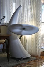
Isn't EJMLC a beauty? ;-)
That you managed to get that from a mold is impressive!
")
Please see attached file amended to explain note #3.
Thanks Bill, for the additional information - I will be having a close look at it.
Kind regards,
David
Hi Bill,
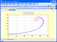
I have tried using your method (as I understand it) but my results become inaccurate near the horn mouth - see the attached comparison with the actual Le Cléac'h horn profile.
Have you validated your calculated results against a reference Le Cléac'h flare?
Kind regards,
David
I have tried using your method (as I understand it) but my results become inaccurate near the horn mouth - see the attached comparison with the actual Le Cléac'h horn profile.
Have you validated your calculated results against a reference Le Cléac'h flare?
Kind regards,
David
Attachments
No!
Hi David,
Thanks for the graphic.
My only concern is that I got the math and geometry right and that your implementation matches it. I suspect that the curves generated are segments of a Cornu Spirals [1] (a project for another day). In any event, I like the slower decline in the radius of curvature at the mouth. That should reduce wave reflectance there. What are the horn parameters that you used? Show me the code please. Note that very small changes in throat geometry may only be magnified at the horn mouth as the function converges on a small circle or point.
Regards,
Bill
Reference [1]
Cornu Spiral -- from Wolfram MathWorld
Hi Bill,
I have tried using your method (as I understand it) but my results become inaccurate near the horn mouth - see the attached comparison with the actual Le Cléac'h horn profile.
Have you validated your calculated results against a reference Le Cléac'h flare?
Kind regards,
David
Hi David,
Thanks for the graphic.
My only concern is that I got the math and geometry right and that your implementation matches it. I suspect that the curves generated are segments of a Cornu Spirals [1] (a project for another day). In any event, I like the slower decline in the radius of curvature at the mouth. That should reduce wave reflectance there. What are the horn parameters that you used? Show me the code please. Note that very small changes in throat geometry may only be magnified at the horn mouth as the function converges on a small circle or point.
Regards,
Bill
Reference [1]
Cornu Spiral -- from Wolfram MathWorld
Hi Bill,
In that case, the isophase wavefront surface areas will no longer expand at a hyperbolic-exponential rate - which is the reason why Jean-Michel developed his profile in the first place....
The same as previously:
Throat diameter = 2.54 cm
Cutoff frequency = 320 hertz
T = 0.8
See Code2.txt attached.
It would appear that your method effectively replicates the results of Jean-Michel’s initial spreadsheet released in 2000. Note however, that an update was provided in 2007 which improved upon the accuracy of the original Le Cléac’h profile. In Jean-Michel’s own words - "the old spreadsheet from early 2000’s was based on a questionable approximation of the curvilinear length of the wavefront".
The screenprint I posted in my last message compared your profile against that generated by my "new" method. The new method produces, I believe, the most accurate Le Cléac’h horn profile achieved to date.
Your equation Rsl = Rst * (Cosh(m * Ls) + T * Sinh(m * Ls)) calculates wavefront radial lengths, but they can only be applied to plane wavefronts for the area expansion to remain correct. Essentially, you are calculating the radii for plane wavefront areas along the length of a hyperbolic-exponential horn having a throat radius of Rst. When these wavefronts are then curved for the purposes of constructing the Le Cléac’h profile (but with the wavefront radial length remaining unaltered) the relationship between radial length and area changes, and the surface areas of the curved isophase wavefronts so generated, no longer expand at the required hypex rate.
This is why it is necessary to consider isophase wavefront surface areas rather than just radial lengths (which would have simplified things greatly). Unfortunately, it is also necessary to use iterative techniques to determine the area of the outer element of a Le Cléac’h horn isophase wavefront - it is simply not possible to find the answer directly.
Kind regards,
David
In any event, I like the slower decline in the radius of curvature at the mouth.
In that case, the isophase wavefront surface areas will no longer expand at a hyperbolic-exponential rate - which is the reason why Jean-Michel developed his profile in the first place...
.What are the horn parameters that you used?
The same as previously:
Throat diameter = 2.54 cm
Cutoff frequency = 320 hertz
T = 0.8
Show me the code please.
See Code2.txt attached.
My only concern is that I got the math and geometry right and that your implementation matches it.
It would appear that your method effectively replicates the results of Jean-Michel’s initial spreadsheet released in 2000. Note however, that an update was provided in 2007 which improved upon the accuracy of the original Le Cléac’h profile. In Jean-Michel’s own words - "the old spreadsheet from early 2000’s was based on a questionable approximation of the curvilinear length of the wavefront".
The screenprint I posted in my last message compared your profile against that generated by my "new" method. The new method produces, I believe, the most accurate Le Cléac’h horn profile achieved to date.
Your equation Rsl = Rst * (Cosh(m * Ls) + T * Sinh(m * Ls)) calculates wavefront radial lengths, but they can only be applied to plane wavefronts for the area expansion to remain correct. Essentially, you are calculating the radii for plane wavefront areas along the length of a hyperbolic-exponential horn having a throat radius of Rst. When these wavefronts are then curved for the purposes of constructing the Le Cléac’h profile (but with the wavefront radial length remaining unaltered) the relationship between radial length and area changes, and the surface areas of the curved isophase wavefronts so generated, no longer expand at the required hypex rate.
This is why it is necessary to consider isophase wavefront surface areas rather than just radial lengths (which would have simplified things greatly). Unfortunately, it is also necessary to use iterative techniques to determine the area of the outer element of a Le Cléac’h horn isophase wavefront - it is simply not possible to find the answer directly.
Kind regards,
David
Attachments
Last edited:
Tool Using, Not Master Serving
Hi David,
There are two issues, one acoustic, and the other involving analytical geometry.
1) Acoustic
The comparative example you gave previously, clearly demonstrates that over 99% of the physical horn length, there is no difference in horn profiles. It is only at the mouth, where the wave front is well outside horn boundaries that a difference in horn profiles occurs. Here wave fronts are undergoing a transformation to a spherical shape, so the isophase surfaces can no longer be equally spaced as may be the case inside the horn body. At higher frequencies the acoustic energy still remains axially concentrated and less affected by lip shape. For mouth lips, the issue is reflectance at lower frequencies. A larger radius of curvature here should reduce the frequency of response ripple onset and its ultimate intensity at [Fc]. This may turn out to be a serendipitous improvement due to a simplification of the method of calculating horn dimensions.
2) Analytic Geometry
Will revisit this issue, particularly in regards to horn lip formation, and respond later.
Note that in both cases for T > 0, Rst > Rot, so the center elements are a set of expanding spherical caps, not flat disks of fixed dimensions.
Regards,
Bill
Last edited:
Hi Bill,
It would be interesting to be able to carry out BEM analyses of the three different profiles, to establish if in fact there are any perceptible differences in the magnitudes of the predicted throat impedance ripples.
I guess one advantage of the latest profile is that the overall horn size is a little smaller....
Noted thanks.
Kind regards,
David
The comparative example you gave previously, clearly demonstrates that over 99% of the physical horn length, there is no difference in horn profiles. It is only at the mouth, where the wave front is well outside horn boundaries that a difference in horn profiles occurs. Here wave fronts are undergoing a transformation to a spherical shape, so the isophase surfaces can no longer be equally spaced as may be the case inside the horn body. At higher frequencies the acoustic energy still remains axially concentrated and less affected by lip shape. For mouth lips, the issue is reflectance at lower frequencies. A larger radius of curvature here should reduce the frequency of response ripple onset and its ultimate intensity at [Fc]. This may turn out to be a serendipitous improvement due to a simplification of the method of calculating horn dimensions.
It would be interesting to be able to carry out BEM analyses of the three different profiles, to establish if in fact there are any perceptible differences in the magnitudes of the predicted throat impedance ripples.
I guess one advantage of the latest profile is that the overall horn size is a little smaller...
.Note that in both cases for T > 0, Rst > Rot, so the center elements are a set of expanding spherical caps, not flat disks of fixed dimensions.
Noted thanks.
Kind regards,
David
Hello,
The last version of the spreadsheet for the calculation of axisymetrical Le Cléac'h horns is 2007.
You can download it at:
http://forums.melaudia.net/attachment.php?aid=2310
(Thanks to the Melaudia association).
Best regards from Paris, France
Jean-Michel Le Cléac'h
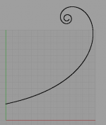
I have downloaded the spreadsheed, and entered the following parameters:
acoustical cut off frequency (Hz) 1100 throat diameter (mm) 25,4 exit angle of the compression driver (°) 5 area of the wavefront at throat
number of facets (for gramophone style horn) 8 T coefficient = 0,8
I then exported columns G and H as a csv file, and imported it as a point cloud in Rhino. The angle is 12,13 degrees. See attached horn profile after importing into Rhino.
Does this mean that I the "exit angle of compression driver" isn't used? Or is there somethin I have misunderstood?
Attachments
Hello Jean-Michel,
This subject has been up elsewhere but I hope you can give your point of view.
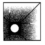
Anyway, lets say we want to build a LeCleach-midbasshorn. Assuming we design it for 100Hz 4*Pi it will be huge. It will be big even if we end it at 90 degrees at a diameter af almost 1,5m.
So is there any way to reduce it when it should be used in 1*Pi ie. sidewall/floor? If it is I guess it would apply to other hornflares too.
I don´t expect an ideal result but maybe an acceptable way to deal with it.
Below is a drawing that I found in Davidenkos site where your spreadsheets are also placed.
This subject has been up elsewhere but I hope you can give your point of view.
Anyway, lets say we want to build a LeCleach-midbasshorn. Assuming we design it for 100Hz 4*Pi it will be huge. It will be big even if we end it at 90 degrees at a diameter af almost 1,5m.
So is there any way to reduce it when it should be used in 1*Pi ie. sidewall/floor? If it is I guess it would apply to other hornflares too.
I don´t expect an ideal result but maybe an acceptable way to deal with it.
Below is a drawing that I found in Davidenkos site where your spreadsheets are also placed.
Attachments
Yes!
Throat tangent angle [Art] (radians) is determined by shape factor [T].
If T = 0 so is Art = 0 as well.
Here the throat area St = pi()*Rot^2 using the ordinal radius of a flat disk.
When T > 0 and Art > 0 as well
Then = Art = arctan(m * Rst * T)
Where [Rst] is the 1/2 the arc length of a spherical cap.
Here St = Pi() * Rst^2 and
Rst = Art * Rot / Sin(Art)
Regards,
WHG
I have downloaded the spreadsheed, and entered the following parameters:
acoustical cut off frequency (Hz) 1100 throat diameter (mm) 25,4 exit angle of the compression driver (°) 5 area of the wavefront at throat
number of facets (for gramophone style horn) 8 T coefficient = 0,8
I then exported columns G and H as a csv file, and imported it as a point cloud in Rhino. The angle is 12,13 degrees. See attached horn profile after importing into Rhino.
Does this mean that I the "exit angle of compression driver" isn't used? Or is there somethin I have misunderstood?
Throat tangent angle [Art] (radians) is determined by shape factor [T].
If T = 0 so is Art = 0 as well.
Here the throat area St = pi()*Rot^2 using the ordinal radius of a flat disk.
When T > 0 and Art > 0 as well
Then = Art = arctan(m * Rst * T)
Where [Rst] is the 1/2 the arc length of a spherical cap.
Here St = Pi() * Rst^2 and
Rst = Art * Rot / Sin(Art)
Regards,
WHG
Exit angle is the full angle of the driver. You can see that by inspecting the "radius of the wavefront at throat:", the expression is =+(B11/2)/SIN(E12/2).
Recommended T is 0.8, but you will not get the same entry angle in the horn as your exit angle of the driver. If you enter the following expression "=ATAN((H25-H24)/(G25-G24))*2" in N25 you will get the entry angle of the horn in radians, by multiplicating with 2 it is easy to compare to the "equivalent to radians cell".
I guess T=0.8 and cut of frequency 500 will give equal angles.
How did you find the exit angle of the Radian? I am looking for the exit angle of 475PB.
How did you find the exit angle of the Radian? I am looking for the exit angle of 475PB.
Thanks.
The corner of the driver has informed Richard (Radian Audio).
My acquaintance requested of it.
I think to you it is necessary to write to it and to ask a question.
Hello,
The exit angle of the driver has nearly no visible influence on the profile of a horn calculated using this spreadsheet.
When the discrepancy of the exit angle of the compression driver and the throat angle of the horn is large the effect of the use of the exit angle is only on the very first elements near the throat.
That parameter ( = exit angle) was initially introduced to reduce some instability on the evolution from step to step of the tangent angle to the profile. (that's the problem when the total number, here 4000, is reduced as in the spreadsheet).
That version of the spreadsheet cannot adapt a horn to a compression driver having a very "different" exit angle...
I have another version which realize a progressive adaptation (something like a spline) at the throat from the exit angle of the compression driver to the "normal" profile.
Best regards from the public library of Loctudy, Finistere, France
Jean-Michel Le Cléac'h (spending some summer vacations)
Friends I ask the help in calculation.
I count (Horn calculation Copyright J.M. Le Cléac'h, 2007) for driver 2" Radian 950PB от 200Hz.
Exit angle of the compression driver (°) = ??? (Value of the whole corner or half
- 10,3 or 20,6???)
T coefficient = ???
Thanks!!!
Jean-Michel Le Cléac'h
Thanks.
I will be grateful other version.
Whether it is possible to make in it new calculation???
E-mail: ylihovol@mail.ru
Thanks.
I will be grateful other version.
Whether it is possible to make in it new calculation???
E-mail: ylihovol@mail.ru
I would like to ask some questions. (I use a 'Maison du haut parleur' Aeria horn from 20 years now )
The first ones about HOMs.
Some people adds foam in their " wave guides " ,. Well, i suppose the idea is that lateral waves will across the foam several time, and it will damp them more than the in-axes ones. ( A llittle like X rays in cancer treatment ;-).
Everybody knows, in closed baffles, than adding damping material increase the acoustical volume, making the charge adiabatic. So my question is:
What is the validity of a calculated horn profile in free air, if you add such damping material, when we know how much few changes in geometry can modify the overall performance..
My second question can look stupid, somewhere i lie on the way the nature respond to problems. Just i noticed than our 'ears horns' are not rigid. Did somebody had tried to build a horn in silicones ? And, if yes, what about the results ? Can-it solve some of the HOM's problems
One of the problems we encounter, when we want to modeling any horn figure, is we don't knows a lot of what happens really at the output of the phase plug of a drive. (this old war flat against spheric )
Would-it be impossible, building a transparent horn, and for any specific driver , to photography the pressures (or speeed) air states, at different frequencies, using smoke and synchronised stroboscopic flashes, or measuring the pressures in the infrared domain ?
(Apologize for my poor English)
Esperado, I remember broaching something similar to your second question with Dr.Geddes in a thread. I think he thought something might be done there but nothing further was discussed. I can't remember which thread it was. I too have thought that there must be a way of keeping the guidance if you like but losing the solidity of the walls, especially as the horn begins to widen out and the pressure drops. Maybe something like a more dense open cell foam.
jamikl
jamikl
- Home
- Loudspeakers
- Multi-Way
- Jean Michel on LeCleac'h horns