Thank you very much for your detailed response.
However, I do not understand why I have no way to measure characteristics of the full range of voltages Vb. Fact all terminals of transistors connected to the push-pull amplifier directly, so no restrictions in terms of conductivity should not be.
However, I do not understand why I have no way to measure characteristics of the full range of voltages Vb. Fact all terminals of transistors connected to the push-pull amplifier directly, so no restrictions in terms of conductivity should not be.
I don't understand what you say.I do not understand why I have no way to measure characteristics of the full range of voltages Vb. Fact all terminals of transistors connected to the push-pull amplifier directly, so no restrictions in terms of conductivity should not be.
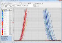
Trouble measuring mulitple Vce-Ic curves
 The first step of the Ib current is set to 5 uA. The next is 10 uA. I repeat the process and eventually the next curve is plotted at about the same Ic level as the previous curve. Then the next curve plots just fine again. If I repeat the whole manual process, starting with highest Ib first, I get the same result. For me, it looks like Ib = 20 uA gets wrong.
The same thing happens, if I do the same process by scripting. Sometimes the last curves seem to be plotted at random Ic levels. I use the Vce-Ic script delivered with the software, slightly modified for may transistor.
The bad tables for the bad curves, contains the same data as the curves display.
Have anybody else experienced the same problem?
Everything else seem to work just fine.
Last edited:
Hi Locky_z,
isn´t time to adopt your software to Windows 10.
The curve tracer is the only reason I have to stay to Win 7.
best regards
What is the problem you are having on win10??
I use it on win10 without any problems.. after fixing the Prolific driver issue...
Use the oldest driver that was supplied to you with the program.
Ha, thank you for reaction, but I use the oldest driver delivered with the program.
I tried all compatibility modes offered, no change.
Nevertheless hearing that you got no problem I will continue trying more.....
No, At first I had problems too..
You have to disable automatic drivers update, as it will override your selection.
Load the old driver manually, Just like in the old days of win98, and select it from the list, you will see several options....
Ha, thank you for reaction, but I use the oldest driver delivered with the program.
I tried all compatibility modes offered, no change.
Nevertheless hearing that you got no problem I will continue trying more.....
It's not the driver it's the hardware....you have to use a prolific chip compatible
with windows 10.
I bought a new adapter and all is working well, you probably have the older chip in your adapter and this in incompatible with win10.
Edit: Sorry confused this with my CNC adapter....but issue is the same: PL2303 chip is not compatible with windows10 driver...for that you need PL2303HXD or later.
From Prolific site:
NOTE:
Windows 8/8.1/10 are NOT supported in PL-2303HXA and PL-2303X EOL chip versions.
Run PL2303 CheckChipVersion tool program in Windows XP/Vista/7 to check chip version.
Windows XP, 2000, 98 and Windows ME driver technical support is discontinued.
Prolific recommends to use PL-2303HXD (HX Rev D) or PL2303TA chip.
Last edited:
It's not the driver it's the hardware....you have to use a prolific chip compatible
with windows 10.
I bought a new adapter and all is working well, you probably have the older chip in your adapter and this in incompatible with win10.
I got it to work on win10 as well.
http://www.airdevilaccessories.com.au/downloads/2050356/PL2303HXA+Windows+8+Driver+Installation.pdf
Enjoy..
Locky-z was so friendly to give me this answer over eBay....
The board that number large than 400# had replace the USB interface chipset with CH340G(USB to serial). and I have tested it can run under windows 10.
I will test the old version that use pl2303 chipset next week.
I installed the old USB to serial driver and it did not work.
This trick worked for me in Win 7
I have tracer #305 so I do not have the chip Locky built in since tracer #400.
Maybe he will find a solution, if not I go on with win7
")
The board that number large than 400# had replace the USB interface chipset with CH340G(USB to serial). and I have tested it can run under windows 10.
I will test the old version that use pl2303 chipset next week.
I installed the old USB to serial driver and it did not work.
This trick worked for me in Win 7
I have tracer #305 so I do not have the chip Locky built in since tracer #400.
Maybe he will find a solution, if not I go on with win7
Success!
Kisses for Beny!
After following your PDF and after a flood of clicks and after canceling a hook that made the Profilec drivers invisible (not compatible)
Then I saw two profiles driver with yellow marks.
First I cancelled the newer one and kept the older one, did not work.
Then I took the newer one (2015) and forced him to use the old profile....then the yellow warning disappeared finally.
It is an odyssey but it works!
Good news for Locky too!
for followers….
one of the problems was that when you install the old driver .exe you do not see the Profilec in the device manager in win 10. You see a neutral driver not called Profilec and you then have to reinstall in this driver window the Profilec driver you see only killing the hook on the note only comparable drivers.
I am so happy that I normally use Mac OSX.
Maybe you can pretend the TL431 is an Nchannel MOSFET:
This "MOSFET" should have a gate threshold voltage of exactly 2.50 volts. So if you select an Ids vs Vgs sweep with fixed Vds = 5.0V, you "should" see zero current when Vgs < 2.50V and infinite current when Vgs >= 2.50V. In other words, a perfectly vertical line at V=2.50V on the curve tracer display. Choose a relatively high value of "base" resistor (= "gate" resistance), so you don't accidentally shove a ton of unwanted current into the Ref pin of the TL431.
edit- you could also short Ref to Cathode and plot it as you would plot a zener diode. You expect the TL431's zener breakdown voltage to be 2.50 volts and its output resistance (DeltaV/DeltaI) to be less than 1 ohm.
- TL431 anode == Source
- TL431 cathode == Drain
- TL431 Ref == Gate
edit- you could also short Ref to Cathode and plot it as you would plot a zener diode. You expect the TL431's zener breakdown voltage to be 2.50 volts and its output resistance (DeltaV/DeltaI) to be less than 1 ohm.
Last edited:
Maybe you can pretend the TL431 is an Nchannel MOSFET:This "MOSFET" should have a gate threshold voltage of exactly 2.50 volts. So if you select an Ids vs Vgs sweep with fixed Vds = 5.0V, you "should" see zero current when Vgs < 2.50V and infinite current when Vgs >= 2.50V. In other words, a perfectly vertical line at V=2.50V on the curve tracer display. Choose a relatively high value of "base" resistor (= "gate" resistance), so you don't accidentally shove a ton of unwanted current into the Ref pin of the TL431.
- TL431 anode == Source
- TL431 cathode == Drain
- TL431 Ref == Gate
edit- you could also short Ref to Cathode and plot it as you would plot a zener diode. You expect the TL431's zener breakdown voltage to be 2.50 volts and its output resistance (DeltaV/DeltaI) to be less than 1 ohm.
Thanks Mark, I'll give it a try
- Home
- Vendor's Bazaar
- Intelligent Curve Tracer 3.0 release