Input a complex load to LTSpice
Hi, All,
I was wondering if anybody know if its possible to place an
complex impedance as. input in the circuit with LTspice?
My goal is to simulate a circuit that has been acoustically been
measured (with TEF). So i got a txt file that has magnitude and
phase.
gr. Marcello
Hi, All,
I was wondering if anybody know if its possible to place an
complex impedance as. input in the circuit with LTspice?
My goal is to simulate a circuit that has been acoustically been
measured (with TEF). So i got a txt file that has magnitude and
phase.
gr. Marcello
Just the answer I was looking for. Have you run it in Ubuntu 15.05 by any chance? Thanks.
It runs very well in linux under wine and auto detects that it is running under wine.
Just Google S-parameter & LTSpice, there are also examples available from the Yahoo LTSpice group.I was wondering if anybody know if its possible to place an complex impedance as. input in the circuit with LTspice?
Just Google S-parameter & LTSpice, there are also examples available from the Yahoo LTSpice group.
Hi,
Indeed, i think is the way to do it. As far as i can read it, its a little bit off topic for me.
Do you know anybody who can wright the equivalent port model of a TXT-file, where the magnitude and the phase expressed in numbers at each frequency?
(a loudspeaker magnitude/phase plot).
gr. Marcello
Do you know anybody who can wright the equivalent port model of a TXT-file, where the magnitude and the phase expressed in numbers at each frequency?
I think so, I believe the model is basically a text file containing the magnitude and phase at each frequency. The best way to learn more about building such model is to join the Yahoo group if you are not a member yet, and download the examples to see for yourself.
Mooly, thanks for answering my question in the vacuum tube section, and thanks for your very helpful tutorial in this thread.
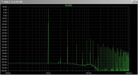
After reviewing that, my basic problem remains. The FFT shows the fundamental at some +5dB, which calls into question the accuracy of all other info on that plot. I believe I have all parameters set reasonably. Can you offer insight as to why this happens and how to correct it?
After reviewing that, my basic problem remains. The FFT shows the fundamental at some +5dB, which calls into question the accuracy of all other info on that plot. I believe I have all parameters set reasonably. Can you offer insight as to why this happens and how to correct it?
Attachments
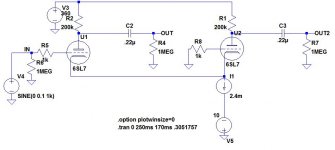
You seem to have an incorrect value for the timestep. Try this,
1/ Delete your .tran command and replace it with,
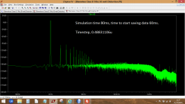
.tran 0 80ms 60ms
That will run for 80ms and start saving data at 60ms. If it needs to run for longer then you can alter it to say .tran 0 800ms 760ms which will run for 0.8seconds and save data from 0.76s
2/ Add the timestep. This is calculated as per post #19.
.options maxstep=0.48831106u
1/ Delete your .tran command and replace it with,
.tran 0 80ms 60ms
That will run for 80ms and start saving data at 60ms. If it needs to run for longer then you can alter it to say .tran 0 800ms 760ms which will run for 0.8seconds and save data from 0.76s
2/ Add the timestep. This is calculated as per post #19.
.options maxstep=0.48831106u
I'm not following the arithmetic. From post #19:
In your example above (post #508), the run time is 80ms-60ms=20ms. Then 20ms/262144=0.0762939uS. How do you get 0.48831106uS?
So, we take our simulation run time which is 2.5ms and we divide that by 262144. The result, 0.00953674us is the value we enter for our "Maximum Timestep".
In your example above (post #508), the run time is 80ms-60ms=20ms. Then 20ms/262144=0.0762939uS. How do you get 0.48831106uS?
I'm not following the arithmetic. From post #19:
In your example above (post #508), the run time is 80ms-60ms=20ms. Then 20ms/262144=0.0762939uS. How do you get 0.48831106uS?
My mistake, I quickly copy and pasted from the earlier post.
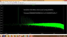
Yes, if you look at the time period of the saved data, 20ms as you say, and you take that and divide by the number of FFT sample points that is selected in LT then you arrive at the timestep figure to enter. The default for the current version of LT is 262144, and you can select lesser values from the dropdown.
If you are using Windows then its easy to use Windows calculator and just copy and paste the result of the calculation directly into LT.
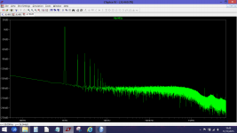
The difference that this error would have made is to raise the noise floor as shown in the attached images.
What is important when running a simulation (and particularly on anything that is AC coupled) is to allow the sim to run for long enough to allow conditions to settle. Another trick is to increase the value of the coupling caps to something ridiculous, so your two 0.22uf caps could be made say 500,000uf for the purpose of the FFT plot.
Attachments
I tried all kinds of different sim times, etc. but still the fundamental is not at 0dB. In fact, looking at your pictures above (post #510) it appears that they too show the fundamental at some 5dB.
Increasing capacitors appears to greatly increase the computation time, so I also tried simply shorting out the capacitors. In that case, the fundamental shows up at some -80dB, so apparently it doesn't like DC in the signal to be measured.
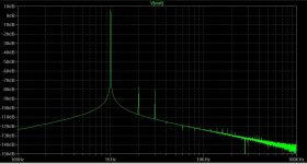
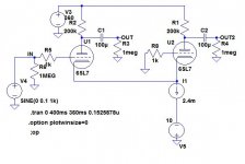
Here is the same circuit with different time frame and large caps. Fundamental still at +5dB and I'm not sure I believe f2 and f3 both at -80dB. And no harmonics beyond 3rd. Seems a little optimistic. And that's the rub. While I'm not particularly concerned with small inaccuracies, I don't yet understand enough about LTspice to know when the results are valid, i.e. when I made a mistake or when I run into an inherent limitation of the sim.
Increasing capacitors appears to greatly increase the computation time, so I also tried simply shorting out the capacitors. In that case, the fundamental shows up at some -80dB, so apparently it doesn't like DC in the signal to be measured.
Here is the same circuit with different time frame and large caps. Fundamental still at +5dB and I'm not sure I believe f2 and f3 both at -80dB. And no harmonics beyond 3rd. Seems a little optimistic. And that's the rub. While I'm not particularly concerned with small inaccuracies, I don't yet understand enough about LTspice to know when the results are valid, i.e. when I made a mistake or when I run into an inherent limitation of the sim.
Attachments
The output of my sim is actually at +9 db reading from the cursor hovered over the fundamental. The level of the input is at approx -17.5db read the same way. So readings by eye from the screen.
That gives a gain of 26.5db (-17.5+9) The amp has a calculated numerical gain of 21 (10k and 500 ohm feedback network). So 1 volt input should give 21 volts output.
Gain in db based on those numbers is 26.44
Kind of messy but its correct.
Your sim looks like it needs to run for longer to take time constants out of the equation.
I don't do the ftt point calc for t_max_step_size
I've mentioned before there's no point in calculating precise t_max_step size for FFT - the solver takes as small and as oddly sized steps as necessary to meet the other accuracy settings
this means the raw is a string of varying time steps and Spice has to interpolate to an exact sampling interval for FFT
so really all you need is at least 2x the time resolution and you're fine - so I use even 1, 2, 5, 100... ns to us depending - but never actually calculate out multiple digits of precision
but you risk missing lots of issues if you don't run at time steps smaller than the fastest device 1/ft
once I see those working stably I might increase max step size for faster sims but still use >10 the resolution needed for the fft size
modern machines are ridiculously fast
I don't do the ftt point calc for t_max_step_size
 There's no answer to that.
........so apparently it doesn't like DC in the signal to be measured.
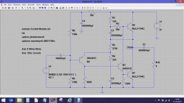
It is 'changing DC' that upsets the simulation. Are you familiar with the JLH69 amp which is AC coupled. Look at the crazy values I've used for the caps.
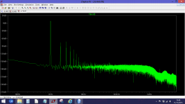
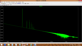
The first FFT is before the speaker coupling cap (so plenty of DC present). The second FFT is after. Even with the large cap, there is still a detectable slant to the trace due to the time constant of cap and speaker. The last FFT shows the effect of changing the speaker cap to just 1000uf.
However, if you look at the harmonics you will see that all three agree, even though the scale at the left has changed and the resolution is poor on the last one.
A bit more on the amplitudes of the FFT. You will find that 0db is referenced to 1 volt rms or 1.414 v peak. So if you set the input signal to 1.414 volts amplitude and look at its FFT you will find it exactly 0db
Attachments
A bit more on the amplitudes of the FFT. You will find that 0db is referenced to 1 volt rms or 1.414 v peak. So if you set the input signal to 1.414 volts amplitude and look at its FFT you will find it exactly 0db
OK, that explains it. Many thanks. I would never have guessed that. Seems illogical. Why pick an arbitrary reference instead of referencing to the actual output, so that the fundamental is always zero dB and you can read the harmonics directly?
As to DC, I believe there are some hidden assumptions there as well. In my same circuit (post #507), if I run the DC operating point sim, I get a DC voltage at the outputs. That DC voltage varies with the capacitor values, but is never quite zero even for small caps. At anything over 500uF, the output is essentially 100V, which is what it would be if the caps were shorted, not open.
So clearly their blank statement that the DC op point routine treats caps as open circuits must be taken with a large grain of salt. Any idea what assumptions are made?
OK, that explains it. Many thanks. I would never have guessed that. Seems illogical. Why pick an arbitrary reference instead of referencing to the actual output, so that the fundamental is always zero dB and you can read the harmonics directly?
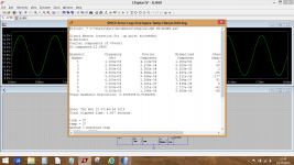
Well we can get more useful information from the FFT.
If you label the output nodes with some relevant tag such as vout and add a new directive (a .op) of,
.four 1khz 10 4 v(vout)
then this gives us the ability to look at the amplitudes of the harmonics with them all referenced to a normalised level of 0db for the fundamental.
And if you had labelled the node Test_Point_1 then the directive would be .four 1khz 10 4 v(Test_Point_1)
The command is made up like this,
four, the command LT needs to do this.
1kHz to match the test frequency.
10, the number of harmonics to be looked at.
4, the last four cycles of the run to base the measurement on.
So we run the FFT as normal and then close the FFT window. Now hover over the circuit on screen (not over the trace window) and right click and select 'view spice error log' and somewhere in the text will be a printout of the harmonics and there amplitudes relative to what is now a 0db fundamental.
Attachments
As to DC, I believe there are some hidden assumptions there as well. In my same circuit (post #507), if I run the DC operating point sim, I get a DC voltage at the outputs. That DC voltage varies with the capacitor values, but is never quite zero even for small caps. At anything over 500uF, the output is essentially 100V, which is what it would be if the caps were shorted, not open.
So clearly their blank statement that the DC op point routine treats caps as open circuits must be taken with a large grain of salt. Any idea what assumptions are made?
I can't explain that without actually seeing it. Some simulations can show odd behaviour but there is usually an explanation (of sorts).
On the JLH simulation I get a DC output voltage 477 femto volts. Its low but not zero. If I open the cap by snipping one end then the voltage is 0.000 volt. So clearly the cap hasn't been treated as totally OC.
Hi all,
I am currently running Multisim and would like compare, the pros and cons of, LTspice versus Multisim. Thank in all in advance.
I've never used Multisim.
I suspect this is a case of what a person is used to and has taken the time to understand and figure out. Same goes for stuff like PCB software. Once you have a grip on one product you are going to prefer that over anything else simply because its familiar.
- Home
- Design & Build
- Software Tools
- Installing and using LTspice IV (now including LTXVII), From beginner to advanced