Howard,
Are you saying that you have two 11x12x30 in boxes that you want to use as subs that also double as stands for your FF85wken's? Are these existing boxes or is that your volume constraint? I will have to add an internal divider because 30 in is not long enough.
No, the boxes are vintage 15 liter ported for the 2 way. The possible freestanding subs would have to be made new. The 11x12x30 dimensions were what I pictured the new boxes looking like if the passage folded back to back(with cabinet panel thickness added), instead of side by side, like the in-wall-cavity-sub that you designed.
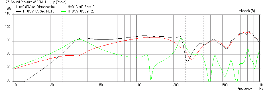
8 in Silver Flute as MLTL Sub
Are you really stuck on the 11x12 in footprint which includes 0.75 in thick boards? I am running into Vb issues and could use a little more volume. Can 13.5 x 13.25 in footprint work? It will help flatten response significantly.
Here is the SPL vs Freq for a 12 in wide x 5.5 in deep (internal dims) channel with a single fold for a 58.5 in long transmission line (30 in tall cabinet with 0.75 in thick walls). Vent is 1.75 in deep x 12 in wide x 14 in long internal shelf vent parallel to walls. Mount driver at 25 in above the floor (0.44x from the closed end). The speaker should be placed as close to a back wall as possible to enhance the bass. A 250 Hz XO point would be ideal rather than 300 Hz.
SPL vs Freq
Attachments

Last edited:
Are you really stuck on the 11x12 in footprint which includes 0.75 in thick boards? I am running into Vb issues and could use a little more volume. Can 13.5 x 13.25 in footprint work? It will help flatten response significantly.
Here is the SPL vs Freq for a 12 in wide x 5.5 in deep (internal dims) channel with a single fold for a 58.5 in long transmission line (30 in tall cabinet with 0.75 in thick walls). Vent is 1.75 in deep x 12 in wide x 14 in long internal shelf vent parallel to walls. Mount driver at 25 in above the floor (0.44x from the closed end). The speaker should be placed as close to a back wall as possible to enhance the bass. A 250 Hz XO point would be ideal rather than 300 Hz.
You don't say it, but it looks like you ARE running sims for the 8" silver flute, rather than the 6.5", and that is what I was wanting for the freestanding, though I do also apologize for getting carried away with new ideas.
And yes, I expected that It would get bigger, although it might be better looking if it was deeper in the room, rather than wider.
It is interesting that it does not go deeper than your sim for the 6.5", so if high output is not a big concern, maybe a 6'5" version is still the best as a sub up to 100hz.
The 250hz x-over would probably work out, though the little fOSTEX FF85WK fullrange is only rated for 5 watts, and is only 86.5 db efficient, so over-all power handling could be an issue. Might work better with another fullrange, like the Fostex FE103, which should play a little louder and lower, and is also very detailed sounding.
Another possible use for the LF unit being simmed:
The really cool thing is that if it could crossover at 250-300hz, then a 2 way passive x-over could be used with the TL as the only LF unit. The TL would then be the woofer of a 2-way, rather than a sub powered by a plate amp supporting/extending a 2-way . So one woofer total, not two.
xrk971
Would a longer line go lower?
Forgot to say it was the 8 on Silver Flute. The bass extension will need a bigger box to Ho deeper. Just switching to a larger driver also requires a box Vb commensurate with different TS params. A passive 2 way XO is a good option with this setup.
Would a longer line go lower?
Part of an earlier conversation with xrk971
Also:What I am wanting to do, now that I have installed my horns (with the Fostex FE166e drivers), is to use an adjacent cavity that is 89” tall, 3.5” deep and about 18.5” wide(about 85 liters) as a sub woofer enclosure. The driver needs to be centered at 19” from one end of the cavity(the upper end, where it will be at the same height as the mouths of my built in horns). I could some fraction of the cavity, but I do want to get some very low frequency response out of the sub.
Seems like some kind of ¼ wave design would be a likely candidate.
I want a driver that would complement the Fostex 166e up to about 100 hz. Maybe a paper cone and powerful motor would be right. It would be good to use a driver that could also function in a 35 liter cab (21x29x3.5"), even if it made less bass. I have a 35 liter cavity on the right side to work with. The 85 liter is on the left side.
xrk971;
Oh OK. Looking again at the built in project, it seems like the 8” would not be the best choice in the 18.5 x 89 x 3.5” left hand cavity. The cross sectional area would work well (18.5x3.5=64.75sq in), but other aspects would not.
8" freestanding design:
The total deal breaker would be the distance from the end (0.44x from the closed end), which would not fit my in-wall situation.
So it seems like the 6.5" is the best bet for the two in-wall cavities that we have discussed. As you pointed out the 6.5” is a good fit for depth and is a good fit for driver position. It should fit my spec (19" to center) for distance from the end(which is the ceiling in this case), because 19" is very close to the 1/3 length, form the closed end, that you spec'd.
It also sounds likely that a 6.5" in the left side 18.5x3.5x89" 85 liter cavity may go lower than it does in the 35 liter cavity, because the CSA could be greater. Hope you will find time for that sim. I know that many folks find AKABAK hard to learn, so I am thankful that you find some time for this. Thanks so much for the work. I have seen that you have a hand in a few threads at a time. Your help is much appreciated.
Oh OK. Looking again at the built in project, it seems like the 8” would not be the best choice in the 18.5 x 89 x 3.5” left hand cavity. The cross sectional area would work well (18.5x3.5=64.75sq in), but other aspects would not.
8" freestanding design:
Here is the SPL vs Freq for a 12 in wide x 5.5 in deep (internal dims) channel with a single fold for a 58.5 in long transmission line (30 in tall cabinet with 0.75 in thick walls). Vent is 1.75 in deep x 12 in wide x 14 in long internal shelf vent parallel to walls. Mount driver at 25 in above the floor (0.44x from the closed end). The speaker should be placed as close to a back wall as possible to enhance the bass. A 250 Hz XO point would be ideal rather than 300 Hz.
The total deal breaker would be the distance from the end (0.44x from the closed end), which would not fit my in-wall situation.
So it seems like the 6.5" is the best bet for the two in-wall cavities that we have discussed. As you pointed out the 6.5” is a good fit for depth and is a good fit for driver position. It should fit my spec (19" to center) for distance from the end(which is the ceiling in this case), because 19" is very close to the 1/3 length, form the closed end, that you spec'd.
It also sounds likely that a 6.5" in the left side 18.5x3.5x89" 85 liter cavity may go lower than it does in the 35 liter cavity, because the CSA could be greater. Hope you will find time for that sim. I know that many folks find AKABAK hard to learn, so I am thankful that you find some time for this. Thanks so much for the work. I have seen that you have a hand in a few threads at a time. Your help is much appreciated.
The total deal breaker would be the distance from the end (0.44x from the closed end), which would not fit my in-wall situation.
This is adjustable to a certain extent. 0.44x is one of the optimal positions, where would you like it? I picked that location so that the driver is located at the top of the 30 in tall cabinet.
You are welcome, I model speakers for fun and am always looking for something new to try Akabak on. Once you get over the initial learning curve, it is not that hard and very flexible, and intuitive (from a code writing standpoint).
This is adjustable to a certain extent. 0.44x is one of the optimal positions, where would you like it? I picked that location so that the driver is located at the top of the 30 in tall cabinet.
I think that since that was the design using the 8", and I am satisfied with the idea of using the 6.5" for both the left and right of the in wall subs, it is not an issue. Driver position was one reason why the 8" was not a good choice for the in wall system, but it may still be for the free standing system.
But the question of what would happen if the 6.5" woofer were used in a channel that is 18.5x3.5" (-65 sq in-the CSA in the 85 liter cavity-which is 18.5x3.5x89") is a relevant question for me. I was wondering if it would go lower than the narrower channel (about 35sq in-as in your first sim which was for the 35 liter cavity), and still be located at 1/3 from the closed end(because 1/3 of 58.5 is about perfect for the in wall installation).
Also I have been wondering if the port shape matters a lot. Could it be round if that was convenient?
I think that I am starting to get a general idea about how the design of these MLTL cabinets works. In a way similar to ported/bass reflex, but encouraging 1/4WL standing waves by making a passage of a certain length. Then, within reason, making the passage CSA larger gives the driver more room to breathe, like in a ported cabinet, and lowers the resonance of the system.
Does this sound right?
Also:
I am not sure why a particular sized vent does what it does, unless this is like a ported cabinet, and so provides a mass of air to load the resonance of the waves inside the cabinet.
I ended up turning a previous horn design I built into a mass loaded design by closing down the mouth. I got better extension, pleasant sounding bass, smoother response, and a significantly smaller cabinet.
Howard,
You are on the right track about MLTL's - see my thread about the Accidental MLTL technique. Basically design a tall aspect ratio bass reflex and calc vent dims with bass reflex but have a box that is between 30 in and 60 in and place vent at one end and driver between 0.2x and 0.5x from closed end. The MLTL effect pulls the bass extension lower and smooths it out. Having a sim lets you optimize driver location and vent location but 0.33x is a good starting point. Shape of vent doesn't matter as long as csa and length are correct. I have converted an open TL to a MLTL and gotten good results too. The term mass loading comes from tuning fork analogy where adding mass to end of fork tine lowers resonant freq.
You are on the right track about MLTL's - see my thread about the Accidental MLTL technique. Basically design a tall aspect ratio bass reflex and calc vent dims with bass reflex but have a box that is between 30 in and 60 in and place vent at one end and driver between 0.2x and 0.5x from closed end. The MLTL effect pulls the bass extension lower and smooths it out. Having a sim lets you optimize driver location and vent location but 0.33x is a good starting point. Shape of vent doesn't matter as long as csa and length are correct. I have converted an open TL to a MLTL and gotten good results too. The term mass loading comes from tuning fork analogy where adding mass to end of fork tine lowers resonant freq.
Hi xrk971,
Do you have time to model a larger MLTL for the 85L cavity ? I figure that we would not end up using all of the cavity, since it is 89" tall. It is 18" wide x 3.5" deep x89" tall. So how much of that width and length would we use to get the deepest response out of the 6.5" silver flute?
Do you have time to model a larger MLTL for the 85L cavity ? I figure that we would not end up using all of the cavity, since it is 89" tall. It is 18" wide x 3.5" deep x89" tall. So how much of that width and length would we use to get the deepest response out of the 6.5" silver flute?
Wave guides for full range speakers, imaging
What effect do short(.75-2", 2-5cm?) wave guides have on controlling dispersion? This build puts the 6.5" FR speakers close to the ceiling (about 9"OC) Thinking about bringing them out form the wall, pointing them down 15-20 degrees and using wave guides to limit interaction with the ceiling and walls.
Is there something about a wall as a baffle that actually messes with the depth of the sound-stage? Psychologically it is hard to picture the sound coming from behind the wall, but what about in terms of measurable data?
Wave guides short like that are good for controlling directivity of high frequencies. If you want to redirect the highs, small horns like that work and can boost HF gain by about 10 dB even. Having a baffle at the wall does reduce the depth of the soundstage because the sound emanates from a source at the wall but imaging is still there. There may be digital signal processing tricks that can be applied to wall speakers to give them more depth (synthetic rear reflections or reverberations).
I am not sure if it would be a good thing to boost the HF at the listening position with these Fostex drivers, but maybe it would be worth it, even if a filter had to be used to even things out if the ceiling reflections could be reduced. Also maybe the filter could be in the form of PVA coating on the whizzer, if it was found that the highs were too intense.
I am also thinking about bringing the drivers out away from the wall; maybe that could help with the imaging.
Any idea about how much space there has to be between a driver/baffle and the wall before baffle step loss becomes an issue?
I am also thinking about bringing the drivers out away from the wall; maybe that could help with the imaging.
Any idea about how much space there has to be between a driver/baffle and the wall before baffle step loss becomes an issue?
I wonder if this low tech trick could work to enhance the soundstage using two center speakers , instead of two rear speakers:
Back in the early seventies, when I was in high school, I read about how to set up rear channels so my stereo could become (quasi) quadraphonic. The set up was/is really simple and I think it was said to extract out of phase signals and feed them into the rears. Not sure what it did technically for sure, but the effect was pleasant as I recall. You simply wire the + on the rears to the + on the amp's front channels, and then connect the two negatives/commons on the speakers to each other. The output of these rears was lower in SPL, and different in content than that of the fronts.
Now I have myself curious, I will have to try this again. Last time was forty years ago.
If 4 channel was quadraphonic then, is 5.1 pentaphonic (+sub)?
If this worked it would be an interesting way to make a dipole speaker, with the drivers on the backside of the enclosure being fed the signal that the 1970's version had going to the rear channels.
Hi xrk971,
Do you have time to model a larger MLTL for the 85L cavity ? I figure that we would not end up using all of the cavity, since it is 89" tall. It is 18" wide x 3.5" deep x89" tall. So how much of that width and length would we use to get the deepest response out of the 6.5" silver flute?
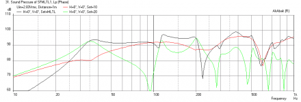
Here is a possible design that is 65 in tall x 18.5 in wide x 3.5 in deep with a 1.75 in x 18.5 in wide x 12 in long slot vent exiting out near the ceiling (or floor). The driver is located at 0.55x (37.5 in) from the closed end.
Attachments
- Status
- This old topic is closed. If you want to reopen this topic, contact a moderator using the "Report Post" button.
- Home
- Loudspeakers
- Full Range
- In-the-Wall Back Loaded Horns