...and don't identify a net as NET_0...when you get to my exalted years you get to thinkin' that they young pup has just grounded the input of the LM317.
oops! That's the fault of my PCB software, as it generates the SPICE files directly from the schematic editor.
Here are my final versions. The key is to put enough current through the voltage divider to put a decent load on the three legged regulator. Also, there needs to be enough current on the adjust pin as well. Per the brief, adding the capacitor on the input of the regulator can cause some undesirable results when the output is sorted, so either don't add this cap and let R3 burn, or be careful what you do with the outputs. This capacitor is really only helpful in lower current situations anyways.
Now I just need to build and verify
")
Attachments
For the filament I had run a pretty heavy gauge wire twisted and used some plastic clips to tie it to the chassis. I have been using kester 2% silver solder but my local vendor cant get it anymore and the replacement brand Qualtek I have not been happy with it. What solder are you guys using? I may wire a single input and output with cat5 just to give it a listen to this weekend.
Bill
Bill
cool, if you happen to have a recommendation, I'd love to hear it!
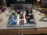
Me, I got around to stuffing my boards. I jumpered the switch location and just stuck the second input jacks on their for the photo. Also, stuck a couple 12v tubes in there for the photo op as well
Getting closer to figure out if this will work Next up is my PSU boards.
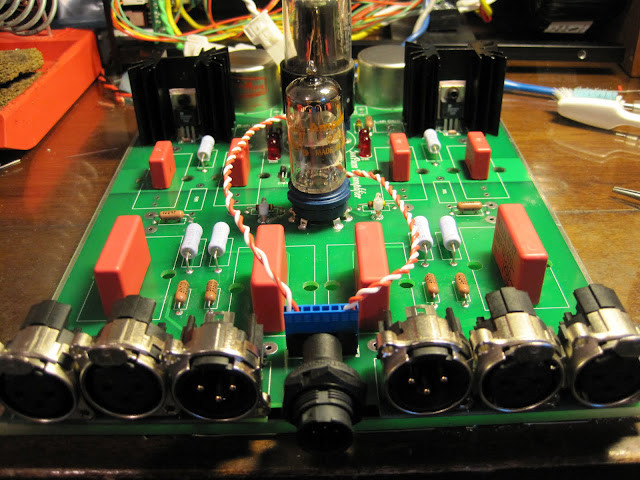
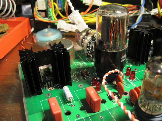
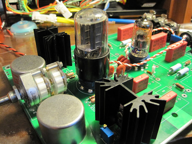
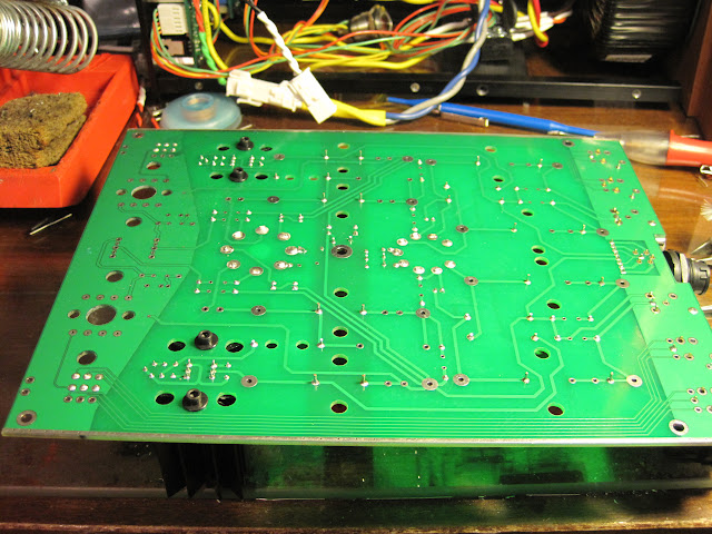
Me, I got around to stuffing my boards. I jumpered the switch location and just stuck the second input jacks on their for the photo. Also, stuck a couple 12v tubes in there for the photo op as well
Getting closer to figure out if this will work
Next up is my PSU boards.
Great! I was bringing my F-4's to audition, but they have been seen plenty. It would be great to have a different pair to audition. And it would be great if I didn't HAVE to bring an Impasse, the pressure is building and it is still about half done! Please tell me as soon as you know you have a working setup or not! We need it!!
Speaking of pressure. I'm working on the replies RIGHT NOW! in fact am procrastinating by checking my threads!
Mark
Speaking of pressure. I'm working on the replies RIGHT NOW! in fact am procrastinating by checking my threads!
Mark
I have been struggling with this, one Chanel plays fine the other is louder with distortion and noise. looking at the output on the scope positive to ground looks good but negative to ground is a mess. Both channels like to oscillate and whistle on power up and settle down when voltage stabilize. I am using a 6922 but ordered a ECC88 replacement to see if the tube itself is the issue.
Bill
Bill
I have some brief results to post. I stuffed my PSU board in the darlington BJT configuration with the LM329, per the second diagram in the National brief. After playing with a few values, the thing is absolutely rock stable with ripple below my measurement capability. My one complaint is the tab on the TIP50 I got is paper thin, so I was thinking about using a pair MJE13005. I'm curious, what makes these (if anything) better choices than the TIP50?
Next I tried the configuration like the first diagram in the brief, but used a single MOSFET pass transistor. The result is very strange. Upon powering up, it comes right to 350V and ripple is below my measurement capabilities. Then as it heats up, everything goes downhill.. after about 5 minutes, the output is down to half the original voltage, and there is appreciable ripple on the output. Load is approximately equal to what the Impasse will draw... Very strange, huh? I'm using the larger reference diode as Jack suggested eariler, and values identical to the brief, with 100 ohm on the gate of the IRF840. R6 is 20K in series with 22K. Perhaps try a BJT instead, or just revert to the temperature compensated (LM329) version, and try this with a MOSFET pass transistor?
Next step is to dial in my CCSes, with the BJT configuration for now
Last edited:
edit:
I think I fixed it. Needed more voltage on the input to the regulator. 50V is a good amount (as SY suggested).
Also, the MJE13005 seem to work great!
edit:
nope, output voltage has dropped and is now stable at 283VDC. Just took longer this time I think, maybe not. Seems to be related to the temperature of the MOSFET?
Last edited:
Always the simple things get overlooked, had the output jack wired wrong on the one channel. Listening to it now on my F4s. Still has a whistle on power up probably need to ad a time delay muting relay on the output. Sound is good slightly leaner than Pumpkin but to soon to really evaluate.
Bill
Bill
Ok, Its only been a couple of hours and I really like this preamp. I tried to listen to it critically but kept getting lost in the music. The F4s have come out as my clear winner of the last five amps I have built. When I upgraded my Xboz to the Pumpkin I was surprised how much more detail there was. This preamp has nice detail but is a little more relaxed, a nice addition to the F4s.
Bill
Bill
- Home
- Amplifiers
- Pass Labs
- ImPasse Preamplifier