Oh my god! does that mean you are going to make an F4 or BA-2? Solid state?I've started a rebuild of mine (it was damaged in two successive cross-country moves) with Jack's PCBs.
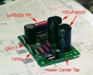
Here's the HV Board installed -- on 1.125" of nylon spacers. It's coming out so that I can put in some paralleled resistors for R103, R104. The initial heat sink for the pass transistor is just some aluminum stock.
It's comming along great Jack!
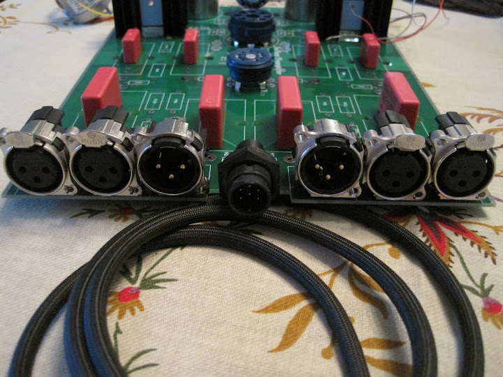
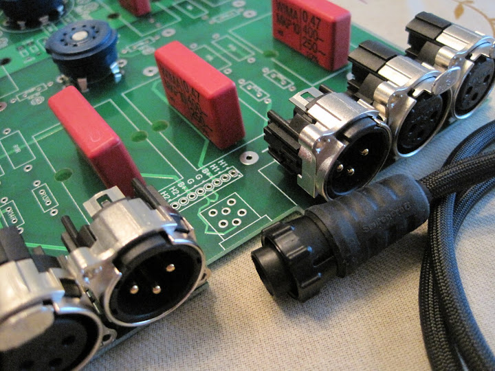
I think I've finalized my prototype boards and am ready to get them made up. When it was all said and done, I expanded the project a bit "just for fun". I wanted to try to make everything PCB mount and fit in a nice aluminum extruded enclosure. It was quite the engineering challenge I found, and somehow I think it's too soon to claim any sort of victory
") I made sure that the PCB mounted devices could be "bypassed" with the use of screw terminals, or pin headers, if the latter ended being a bad idea somehow.
I made sure that the PCB mounted devices could be "bypassed" with the use of screw terminals, or pin headers, if the latter ended being a bad idea somehow.Anyways, if anyone is interested in stuffing a board and enjoying in one man's madness (mine) then please contact me and we can go from there, I think I have one board available
larger photo available here, or via e-mail if you'd like:
http://picasaweb.google.com/lh/photo/bELTxN55EIhWgVdUhbzGzg?feat=directlink
Dave -- on my power supply boards I used the R016_7 -- 3 watt from either Xicon or Speer -- I would suggest that you use a 5W which has lead spacing of 25mm. It will run cooler. The resistor should also be mounted with some clearance from the board.
The BC resistors I'm using only seem to go up to 3W. Mouser part number 594-5093NW22K00J. I do have room for a 25mm LS resistor, but it will be very tight. I'm assuming you mean these:
http://www.koaspeer.com/pdfs/res52.pdf
It's comming along great Jack!
I think I've finalized my prototype boards and am ready to get them made up. When it was all said and done, I expanded the project a bit "just for fun".
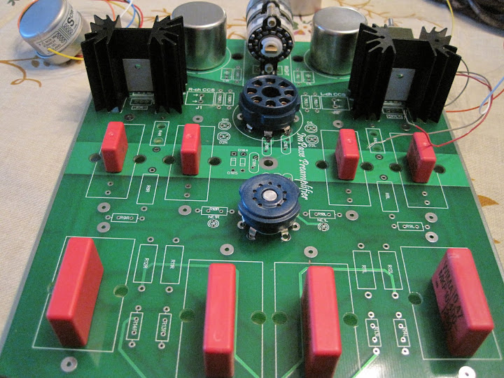
One more thing -- you want to be able to trim the values of the resistors on the depletion MOSFETs -- R6 and its analog -- start with a value higher than 120 ohms and parallel in values until you get the exact bias current you need. If I were to do my boards again I would allow for another set of vias for the paralleled resistor value.. SY Describes the method for getting the right value.
One more thing -- you want to be able to trim the values of the resistors on the depletion MOSFETs -- R6 and its analog -- start with a value higher than 120 ohms and parallel in values until you get the exact bias current you need. If I were to do my boards again I would allow for another set of vias for the paralleled resistor value.. SY Describes the method for getting the right value.
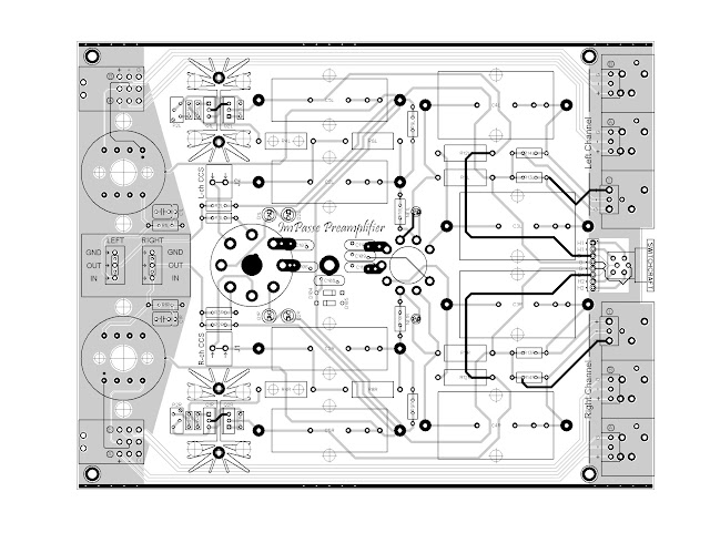
In fact I added the trim pot and the "CCS Jumper" exactly for that reason. All one needs to do is populate the CCS and set the trimmer plus series resistor at the approximate value in the text, then stick an ammeter over the jumper and trim until the desired current shows on the ammeter. Once it's set, then jumper this location. No matching required. This same spot can also be used to plug in an "external CCS" in, perhaps one of Gary Pimm's multitude. Also, this variable resistor allows for different bias points to be explored with relative ease.
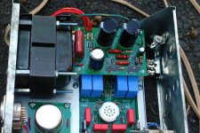
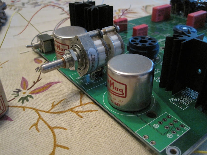
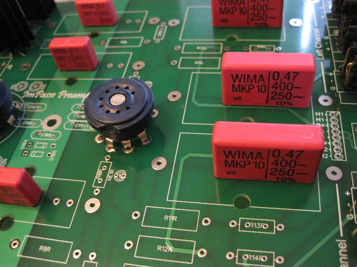
well, my Impasse boards arrived and all the big stuff fits! That's a nice feeling I plan on building and testing my HV supply boards tonite and then start stuffing the monster board this weekend.
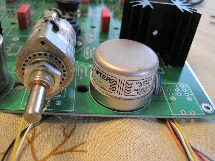
I decided to use a toggle switch for input selection that moves right to left instead of up and down, as it simplified the layout considerably.
Unfortunately, I don't really have an amp to test this with at the moment, as my F4s are in disrepair... I'm assuming a 300 ohm pair of headphones wouldn't make this preamp too happy, huh?
I plan on building and testing my HV supply boards tonite and then start stuffing the monster board this weekend. I decided to use a toggle switch for input selection that moves right to left instead of up and down, as it simplified the layout considerably.
Unfortunately, I don't really have an amp to test this with at the moment, as my F4s are in disrepair... I'm assuming a 300 ohm pair of headphones wouldn't make this preamp too happy, huh?
Uncooperative maida
Ok, I ditched my point to point temp compensated maida and purchased one of Jacknj fine boards. I still am not getting full output voltage only 270V. I have 385V going into the tip50 but only 270V out. I am using a 1n4742a zener for d103 and it is positioned correctly. Due to high voltage I am not my usual rambunctious self and am shying to the side of advise on the subject. I am loading the output of the regulator with 12k.
Thanks
Bill
Last edited:
Curious side bar, is that a reference to a comic I recalled from my youth while living Brussels in the 60 s?
Bill
No, the Brooklyn Public Library decided that TinTin was morally offensive. I think the Belgian consulate should protest. Throughout the 80's my wife and I would read the comics to our kids when we traveled to Fr. and Be.
My Impasse power supply board is driven by the transformer recommended by SY -- the little Dyanco jobbie was running out of gas and would wimp out as the preamp pulled power.
Last edited:
Ok, I ditched my point to point temp compensated maida and purchased one of Jacknj fine boards. I still am not getting full output voltage only 270V. I have 385V going into the tip50 but only 270V out. I am using a 1n4742a zener for d103 and it is positioned correctly. Due to high voltage I am not my usual rambunctious self and am shying to the side of advise on the subject. I am loading the output of the regulator with 12k.
Thanks
Bill
I'd be looking at the set resistors and the voltages across them. I'd also scope the output to ensure that you don't have any oscillation.
I'd be looking at the set resistors and the voltages across them. I'd also scope the output to ensure that you don't have any oscillation.
When I used the Dyna transformer I had no oscillation. I used the temperature comp regulator, the straight darlington, and the LastPAS regulator. The darlington power supply regulator is the one I used when making the THD measurements (which confirmed SY's results). The preamplifier worked beautifully when I drove the regulator with 400V from my Heath IP-17 power supply, but when I used the little guy it fell on its face. There was no oscillation, however.
Wiggler -- you could be starving the pass transistor for drive.
I searched for the original Maida paper with no luck. When you refer to the set resisters are these R5 and R6? I seem to have 385V going into U2 and 270V out of it. How would I determine if it is starved? I am loading the output with 12k 5W resisters. I will check for oscillation when I get home.
Thanks
guys
Thanks
guys
- Home
- Amplifiers
- Pass Labs
- ImPasse Preamplifier