SY:
I didn't get a chance to add a capacitor, but I'm curious to its effect. Does it straighten up the waveform a bit? Here are my measurements.
I tied together all the leads on the primary and injected the signal on the red wire. The was connected to one probe, and my Tek CFG280. Signal was measured on the scope to be a 4dBu sine wave, then I hit the square wave button. (not all that scientific, but I tried). The other probe was connected to the yellow wire, and the ground clip to the orange wire.
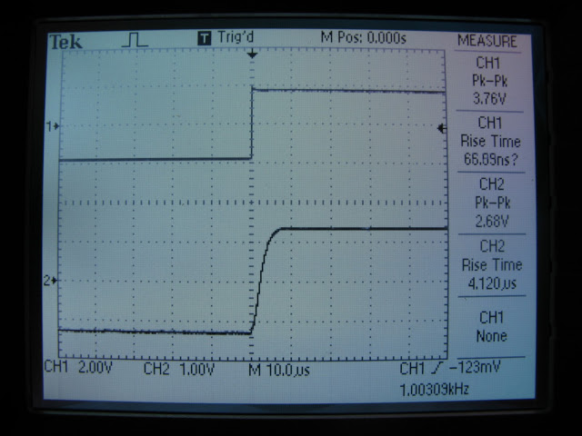
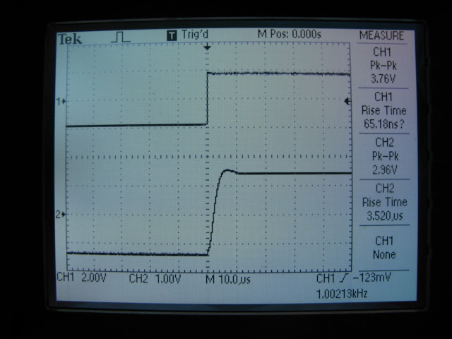
First test was 10K across the secondary:
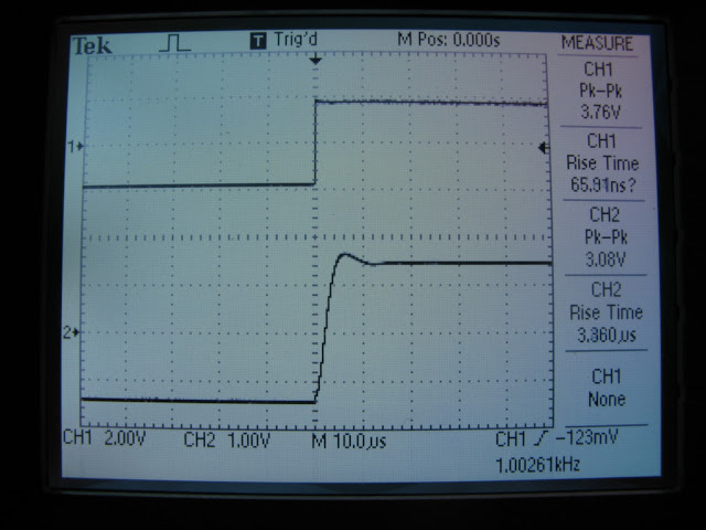
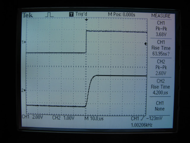
Then 15K:
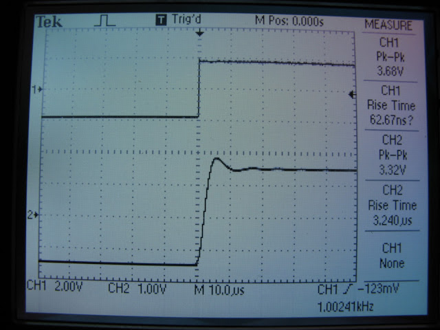
Then 18K:
Then I decided to pull out a crappy heat gun for stripping paint and try to see if I could induce some noise into the transformer..
Tried all kinds of configurations, but no noise, even in peak detect acquisition mode.
Then I was wondering... should I take the 100K pot into consideration? Also, this would give me slightly different measurements... so I did the following:
100K || 18K
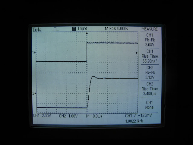
100K || 15K
100K || 10K
Anyways, yeah a pot would have been smarter, huh
So, was this testing quasi correct? Of course, I'll just use your final values, but it was a rather fun experiment")
I didn't get a chance to add a capacitor, but I'm curious to its effect. Does it straighten up the waveform a bit? Here are my measurements.
I tied together all the leads on the primary and injected the signal on the red wire. The was connected to one probe, and my Tek CFG280. Signal was measured on the scope to be a 4dBu sine wave, then I hit the square wave button. (not all that scientific, but I tried). The other probe was connected to the yellow wire, and the ground clip to the orange wire.
First test was 10K across the secondary:
Then 15K:
Then 18K:
Then I decided to pull out a crappy heat gun for stripping paint and try to see if I could induce some noise into the transformer..
An externally hosted image should be here but it was not working when we last tested it.
Tried all kinds of configurations, but no noise, even in peak detect acquisition mode.
Then I was wondering... should I take the 100K pot into consideration? Also, this would give me slightly different measurements... so I did the following:
100K || 18K
100K || 15K
100K || 10K
Anyways, yeah a pot would have been smarter, huh
So, was this testing quasi correct? Of course, I'll just use your final values, but it was a rather fun experiment
First, let me say that I'm envious of your storage scope! And you've done a nice demonstration of the virtues of a good input transformer.
The RC combo gets rid of some ringing that I saw in mine when terminated by 15k. Now, that ringing is also dependent on the source resistance, so YMMV greatly. I used a 600R source for my measurements, your was probably lower, judging from the waveforms you're showing.
The RC combo gets rid of some ringing that I saw in mine when terminated by 15k. Now, that ringing is also dependent on the source resistance, so YMMV greatly. I used a 600R source for my measurements, your was probably lower, judging from the waveforms you're showing.
First, let me say that I'm envious of your storage scope! And you've done a nice demonstration of the virtues of a good input transformer.
The RC combo gets rid of some ringing that I saw in mine when terminated by 15k. Now, that ringing is also dependent on the source resistance, so YMMV greatly. I used a 600R source for my measurements, your was probably lower, judging from the waveforms you're showing.
Thanks! My source impedance was 150 ohms, straight from my function generator. I'm just beginning to understand the importance of impedance in testing jigs, as I ran into a case this week where I needed to divide a signal down -60dB from my function generator and was surprised to not get what I thought I would.
Can you explain why you did the testing with (10K + 220pF) || 15K? I don't understand the 15K, as the next element is the 100K pot? The 600R source is what is mentioned on the datasheet. So, is it the case that you'd expect the values you choose with 600R to work well with lesser input impedance (i.e. 600R is a "worse-case" scenario?), or is more that is some sort of standard value to use.
Thanks!
Last edited:
Can you explain why you did the testing with (10K + 220pF) || 15K? I don't understand the 15K, as the next element is the 100K pot? The 600R source is what is mentioned on the datasheet. So, is it the case that you'd expect the values you choose with 600R to work well with lesser input impedance (i.e. 600R is a "worse-case" scenario?), or is more that is some sort of standard value to use.
The 600R was arbitrary, representing my worst source. With that source and a 25k pot (which is what I'm using), there were three cycles of overshoot. To be honest, there was nothing systematic, I just chunked in various Rs and Cs until the square wave looked right. It still looked OK with a 50R source, so I soldered that Zobel in.
With just a 100k pot and no resistor across it to bring the load down, you can come up with a Zobel to get rid of the ringing, but the source impedance becomes MUCH more critical- change it just a bit and the Zobel doesn't do its job.
The 600R was arbitrary, representing my worst source.
Nah, you probably worked for the phone company. What's a dBm without 600R anyway?
Heard someone once say "This function generator is all screwed up..." -- he forgot to terminate it with 50R.
I was wondering about R101 and R102, which are in series with the rectifier diodes. Are these values chosen specifically for the UF4007?
No, they're chosen specifically for that transformer. The idea is to drop some voltage (it comes out too high otherwise) and limit ripple current, all in one go. If you use a transformer with a higher resistance secondary, those can be reduced.
No, they're chosen specifically for that transformer. The idea is to drop some voltage (it comes out too high otherwise) and limit ripple current, all in one go. If you use a transformer with a higher resistance secondary, those can be reduced.
ah. if this is the case, what's the difference between sticking one before each diode, and a single resistor (or two in parallel, if the answer is power dissipation) afterward rectification?
I have a question on the power supply. The portion where ground connects to two diodes and a ceramic cap with one leg of the cap going to earth and the other goes where? It has a nice little arrow, but I have no clue where it is going.
Hopefully with that bit of knowledge my power supply will be up and running and my impasse shortly thereafter.
Hopefully with that bit of knowledge my power supply will be up and running and my impasse shortly thereafter.
I have a question on the power supply. The portion where ground connects to two diodes and a ceramic cap with one leg of the cap going to earth and the other goes where? It has a nice little arrow, but I have no clue where it is going.
Hopefully with that bit of knowledge my power supply will be up and running and my impasse shortly thereafter.
Dave:
This is a ground loop breaker and connects the PSU ground to the chassis earth. There's a notation somewhere that shows that all the arrows go to ground in a "christmas tree" style ground configuration.
Hi Marc
Thanks for the schematic. It cleared up the questions I was looking to answer. I got the power supply up and running this time. 364 volts out and solid as a rock. That's what I wanted to see. I wired everything up last night, and ready to test. At that point it was pretty late so I went to bed without knowing if it is working right or not. I have the house to myself tonight, so if everything goes well, I should be listening to a new Impasse pre.
Thanks for the help. Now lets just keep our fingers crossed that I don't have any issues with the rest of the build. I would post pictures, but right now it is mounted up to a piece of plexi with the pot and connectors held down with hot glue. Steps... baby steps. Get it running first then build the box.
Dave
Well, I got everything wired up and making music tonight. Unfortunately, I have a huge amount of distortion at volume. When the level is turned down to a conversational level, the distortion is quite low. When I increase the volume to a normal listening volume the distortion takes over. It definitely peaks with the amplitude peaks. Any ideas of where to start looking first?
It cleared up the questions I was looking to answer
glad I could help!
- Home
- Amplifiers
- Pass Labs
- ImPasse Preamplifier