I never understood why isobaric mounting reduced
The box size by 1/2. Maybe someone will explain?
The acoustically close coupled drivers now have double the moving mass [Mms] and half the suspension compliance [Vas] of a single driver, so box size is halved.
GM
It may be crossing over into a 2 stage diaphram pump design that I have seen. without the check valves in vapor lock condition.
Only one way to find out if it works. Or what it does.
Build and test.
Testing requires actual measurements if you want to have any idea at all of what's happening. A simple listening test will only tell you if you subjectively prefer the sound before vs after. Nothing else.
I don't think most things are dicovered in simulators. Although they are much better understood in them.
I don't know how things are usually discovered but new inventions typically are based on a solid foundation of the physics and behavior of elements at hand.
It would be a lot easier to "discover" what's going to happen with a simulator. But if you want to go the build and test empirical route that's fine too, as long as you understand that in this situation the chance for success is overwhelmingly low (especially since you haven't actually defined any goals concerning what you want to happen and the fact that the 2 new chambers resulting from cutting the coupling chamber in half are VERY small in the context of the cab bandwidth), and you won't learn much (if anything) without doing measurements before and after.
You know, I thought I would never say this.
I think this one is finished.
Your assessment is sound.
Harnessing center chamber is better done on the next project.
My subjective opinion is, I love it.
For what this thing is, its size with 2-10"s, it sounds fantastic. I'm just adding a few details your sugestions 50mm port , abit more flare round the inside corners and cover it all in epoxy resin. and call it done.
Thanks" Just a guy".
I think you under estimate yourself. You have put up with my ignorance and hung in there. I know it's hard to take someone's opinion without hard data. I'm happy with this and I'm pretty paticular about my bass sound. It's a fun project when it sounds good.
I'll post more pics.
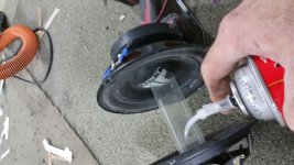
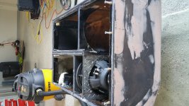
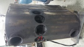
Here the port was extended to 50cm.
I put foam to give a solid feel. Rather loose a little cu ft. Than have a ringing port.
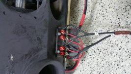
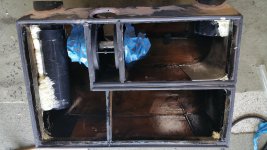
Laminated diamond plate because there wasn't much meat for the speaker bolts to connect to.
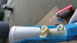
Also heated some pcs of linoleum flooring and bent them creating curved inside corners. Foam the void.
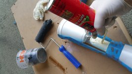
Then I covered the whole thing with fiberglass resin.
I put foam to give a solid feel. Rather loose a little cu ft. Than have a ringing port.
Laminated diamond plate because there wasn't much meat for the speaker bolts to connect to.
Also heated some pcs of linoleum flooring and bent them creating curved inside corners. Foam the void.
Then I covered the whole thing with fiberglass resin.
Attachments
...
The coupling chamber is completely omitted in this sim. I did fool around with adding it in Akabak, both with the coupling chamber ported and closed. And since I was not able to physically connect the cones it did make a bit of difference in the sim (since both drivers have a different load presented to them they won't move in identical fashion) so the frequency response was slightly different and there was a bit of output from the port. ...
You can maximise the coupling "rigidity" in AkAbak by making the enclosed volume very small (0.1 cm2 etc). You also need the mass of the coupler, and the mass of the air in the real-world chamber if you want to be pedantic.
You can maximise the coupling "rigidity" in AkAbak by making the enclosed volume very small (0.1 cm2 etc). You also need the mass of the coupler, and the mass of the air in the real-world chamber if you want to be pedantic.
You can maximize the coupling rigidity even more by eliminating the coupling chamber entirely and simulating the two drivers as one unit.
The whole point here was that I would have liked to simulate it EXACTLY as it is. And it's impossible. If you simulate it as 2 separate drivers with a coupling chamber there's no way to make the coupling chamber the correct size and have it ported AND have the drivers physically connected. it's just not possible, and your suggestion of making the coupling chamber small doesn't allow you to simulate the design exactly as built OR couple the drivers any better than simulating them as a single unit without a coupling chamber.
It may take a bit more wattage to drive this thing.
Although the payoff is the super low frequencis it hits. Can you only get the really low stuff when the speaker has enough mass. Ie 15" 18" or are these frequencies possible with a smaller lighter speakers?
Absolutely, you can tune the box to produce whatever frequencies you want. You could tune your box to 3 hz if you wanted to. But the cost is sensitivity (if the box remains the same size) or size (if you make it a lot bigger to increase sensitivity). If you did port your box to 3 hz it would have a rising response (low sensitivity at low frequencies).
You can put a tweeter in a ported box tuned to 3 hz if you wanted to. it wouldn't play very loud at 3 hz and it would have terrible low frequency sensitivity and dramatically rising response at higher frequencies but it is something you can do.
Im not sure whats going on with the new 50cm port. it seems to have lost its spunk.
just as you predicted it was chuffing a little at extreme volume I polished and flared both ends now its minimal it has allways been the dominate port but now it seems like its doing 95% of the work.
Is there another harmonic length I can try I don't care how long. I have a 20 foot stick. Otherwise I might have to shorten it again??
The sims I showed in post 36 clearly show that was going to happen. You trade sensitivity for lower extension, that's the rule if you don't dramatically change the size of the box. You lose about 10 db from the lower tuned chamber but you didn't change the output of the higher tuned chamber.
You can't easily make the volume of the lower tuned chamber bigger so all you can do with that chamber is change the tuning. You can shorten the port and gain sensitivity but you lose the low frequency extension. Or you can play with the small chamber. You can change the port length or make the chamber smaller. Ideally it should be simulated so you know what to expect before making changes.
Or you can just eq the low frequencies up or the high frequencies down and not change the box at all. Depends what you want to do. But the only way to increase the low frequency sensitivity is to make the box larger. Or raise the tuning and trade the low frequency extension for higher tuning.
If you put 2x ~12-13" long ports in the small box and cut the big box one back to 6" you should get more output before chuffing.
If you want more punch, go for a 3" long vent in the large chamber (or better 2x 6" long) along with the 2x ~12" vents in the smaller chamber. Best to cut out everything below ~25Hz with this one...
If you want more punch, go for a 3" long vent in the large chamber (or better 2x 6" long) along with the 2x ~12" vents in the smaller chamber. Best to cut out everything below ~25Hz with this one...
Thanks
I'll start with the 2 equal lengths of 12 x 3 7/8" I'd pipe in the small chamber. The chuffing is not bad bad. But I was looking for a way to get more sound through 2 ports. I was thinking of more ports of unequal length or diameter but, I know better after reading up on it.
I'll start with the 2 equal lengths of 12 x 3 7/8" I'd pipe in the small chamber. The chuffing is not bad bad. But I was looking for a way to get more sound through 2 ports. I was thinking of more ports of unequal length or diameter but, I know better after reading up on it.
If you put 2x ~12-13" long ports in the small box and cut the big box one back to 6" you should get more output before chuffing.
To expand on this a bit, if you put 2x 12 inch ports in the small box and 2x 12 inch ports in the large box you will get exactly the same frequency response and excursion you started with but the velocity in the ports will be cut roughly in half. That's a good thing.
To be even more clear, double up the amount of ports in both chambers and make them all 12 inches long and you will have the same response but with half the port velocity.
The velocity is still incredibly high though.
If you want more punch, go for a 3" long vent in the large chamber (or better 2x 6" long) along with the 2x ~12" vents in the smaller chamber. Best to cut out everything below ~25Hz with this one...
This more punch version will indeed have more punch than what you had before, along with higher sensitivity, a narrower passband and a higher tuning.
Here's a quick sim compared with what you had before. Dark trace is the more punch version, light grey trace is the original version.
This is going in the opposite direction of the 50 cm long port, instead of a lower tuning this will give a higher tuning. The doubled up ports are still a good thing though, they do cut velocity considerably but it's still very high.
An externally hosted image should be here but it was not working when we last tested it.
- Status
- This old topic is closed. If you want to reopen this topic, contact a moderator using the "Report Post" button.
- Home
- Loudspeakers
- Subwoofers
- Id rather be lucky than tallented. Isobaric 6th order band pass