That's what Chick Hern use to say.
I guess if you build enough boxes using basic rules of thumb, one of them is bound to sound good. Considering all the Harmonics and different advancements for the past few years. these subwoofers have accomplished, The incredible SPL and low response. its truly amazing. as human beings we have never heard these sounds before.
Ive been building boxes for 35 to 40 years, and played around with many designs trying to get that 20hz pressure wave resonance.
I use to think the best bass sound came from an Ampeg SVT or Portiflex B-18. but you car audio guys have taken it to the next level.
When I found WinISD, I went crazy and designed 50 or 60 boxes to figure out what my next build would be. Most of my past successes were giant refrigerator TL ported with multiple 18" drivers. (how can I miss with that) Except that wont fit in my car. so I set out to build with some size constraints. I studied all the designs and read all the blogs. and figured I would build the most complicated box configuration I could think of, just for an experiment and see where it lead. I had a couple of new Orion XTL 10"s and decided on
"6th order band pass Isobaric mount"
most of the stuff I read said this had to be exact. and the only reason for isobaric was to save space or make some crappy drivers sound good. When I got to the point where I could try this box out I couldn't wait to plug it in.
It was somewhat disappointing and the warnings and speculations seemed true. WINISD called for a 18" and 28" port. Orion called for a 1 CU.Ft. box with a 9" port for ea. driver. The thing sounded okay but nothing special. I tried changing the phase and opening up the center chamber, different combinations of coil configurations( each driver has 2-2ohm coils) still nothing special. then I rembered
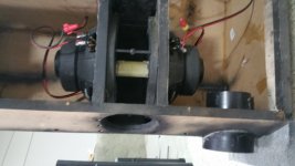
There was this one guy (I wish I caught his name, maybe he will read this and chime in?) who came up with all these ideas. one of the ideas was connecting the cones. Why not, I might as well take a risk. I already welded bolts between the driver baskets and sealed them in this box. It wasn't going to be easy getting them out. I checked WINISD for added moving mass and the low Hz scale was off the charts. I took this mylar tube I got from a fluorescent light protector and cut it to fit, then I stuck it between the cones and filled it with expanding foam. I had to wait a day for it to dry.
I had to be sure the phasing was right, or I would destroy my speakers. I used the old battery trick. I wanted them in series incase one dropped out the other would not tear them both up. I took both voice coils on each driver and wired them in series then series again with each other = 8 ohms
I knew I was going to need some massive power. so 12ea 6v6 pp monster it is. ??watts.
Good Lord,
This thing sounded so good, I almost wanted to cry.
I don't know if the band pass porting is creating even harmonics or what but the isobaric set up with added mass was making a super tight massive low end like Ive never heard!!
The ports create an even pleasant pressure wave at extreme volume pumping up the 15k square foot where house. with 2-10s I tweaked the ports. and am thrilled this is my best work yet. I want to thank the guy who came up with the cone connection idea. I will take pictures and include dimensions in the next couple of days it still looks pretty ugly. I just had to tell somebody.
Ive had some pretty dismal boomy boxes. and some really good ones but this thing is on a level of its own. ( Lucky )It might be impossible to calculate harmonics on harmonics on harmonics so luck has to be in the equation.
Cheers.
I guess if you build enough boxes using basic rules of thumb, one of them is bound to sound good. Considering all the Harmonics and different advancements for the past few years. these subwoofers have accomplished, The incredible SPL and low response. its truly amazing. as human beings we have never heard these sounds before.
Ive been building boxes for 35 to 40 years, and played around with many designs trying to get that 20hz pressure wave resonance.
I use to think the best bass sound came from an Ampeg SVT or Portiflex B-18. but you car audio guys have taken it to the next level.
When I found WinISD, I went crazy and designed 50 or 60 boxes to figure out what my next build would be. Most of my past successes were giant refrigerator TL ported with multiple 18" drivers. (how can I miss with that) Except that wont fit in my car. so I set out to build with some size constraints. I studied all the designs and read all the blogs. and figured I would build the most complicated box configuration I could think of, just for an experiment and see where it lead. I had a couple of new Orion XTL 10"s and decided on
"6th order band pass Isobaric mount"
most of the stuff I read said this had to be exact. and the only reason for isobaric was to save space or make some crappy drivers sound good. When I got to the point where I could try this box out I couldn't wait to plug it in.
It was somewhat disappointing and the warnings and speculations seemed true. WINISD called for a 18" and 28" port. Orion called for a 1 CU.Ft. box with a 9" port for ea. driver. The thing sounded okay but nothing special. I tried changing the phase and opening up the center chamber, different combinations of coil configurations( each driver has 2-2ohm coils) still nothing special. then I rembered
There was this one guy (I wish I caught his name, maybe he will read this and chime in?) who came up with all these ideas. one of the ideas was connecting the cones. Why not, I might as well take a risk. I already welded bolts between the driver baskets and sealed them in this box. It wasn't going to be easy getting them out. I checked WINISD for added moving mass and the low Hz scale was off the charts. I took this mylar tube I got from a fluorescent light protector and cut it to fit, then I stuck it between the cones and filled it with expanding foam. I had to wait a day for it to dry.
I had to be sure the phasing was right, or I would destroy my speakers. I used the old battery trick. I wanted them in series incase one dropped out the other would not tear them both up. I took both voice coils on each driver and wired them in series then series again with each other = 8 ohms
I knew I was going to need some massive power. so 12ea 6v6 pp monster it is. ??watts.
Good Lord,
This thing sounded so good, I almost wanted to cry.
I don't know if the band pass porting is creating even harmonics or what but the isobaric set up with added mass was making a super tight massive low end like Ive never heard!!
The ports create an even pleasant pressure wave at extreme volume pumping up the 15k square foot where house. with 2-10s I tweaked the ports. and am thrilled this is my best work yet. I want to thank the guy who came up with the cone connection idea. I will take pictures and include dimensions in the next couple of days it still looks pretty ugly. I just had to tell somebody.
Ive had some pretty dismal boomy boxes. and some really good ones but this thing is on a level of its own. ( Lucky )It might be impossible to calculate harmonics on harmonics on harmonics so luck has to be in the equation.
Cheers.
Okay
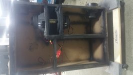
I'm not going to win any woodworking awards.
It's a prototype I didn't expect it to sound so amazing.
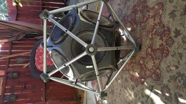
I stuck in a picture of an older speaker I built just because it's interesting.
I have been pushing this isobaric setup at pretty high volumes for 10 hours a day for a few days now.
Had to seal a couple screw holes. But this thing is incredible, I'd like to think my box had something to do with it but, the more I think about it, the connected isobaric setup would probably sound outstanding even in 2 five gallon buckets.
The foam/mylar connector is holding up nicely.
I did a pretty sloppy job but the beauty is in the sound. I'm beginning to think it doesn't matter but.
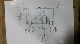
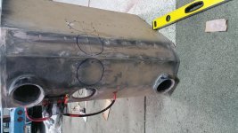
1st chamber is 3.5 cu ft.
2nd chamber 1 cu ft.
I tried many port lengths and found 7" to sound best
4 " diam. I. D with flanged ends. No loss of low end with shorter lengths.
I will try putting some bricks in the 3.5 cu. Chamber
And bring it to 1 or 1.5 cu. Just because I think it will still sound great and be much more practical for my car.
Has anyone built connected isobaric before?
I would think the R&D guys at EV Or JBL have tried everything.
Also is there anybody around Los Angeles who would help test this thing.
There are some super smart and talented guys on this website
Who probably think I'm an idiot. You are right in some regards. Although I do know when the Bass is sounding very good. I was lucky enough to work at Sound City for several years . And fortunate enough to know Tom Skeeter, who was the reason the place was so sucsessful. not so much the Neve, Stewter analog stuff. Alhough I Remember this secret device that was given by George Martin that the vocals ran through. I will put it in a different string.
One of my refrigerator cabinets is probably still there. Thanks for reading. If you are thinking of building a sub woofer.
This connected cone, 4 coil isobaric. Is the best sounding setup I have ever heard. You won't be dissapointed. Go for it.
I'm not going to win any woodworking awards.
It's a prototype I didn't expect it to sound so amazing.
I stuck in a picture of an older speaker I built just because it's interesting.
I have been pushing this isobaric setup at pretty high volumes for 10 hours a day for a few days now.
Had to seal a couple screw holes. But this thing is incredible, I'd like to think my box had something to do with it but, the more I think about it, the connected isobaric setup would probably sound outstanding even in 2 five gallon buckets.
The foam/mylar connector is holding up nicely.
I did a pretty sloppy job but the beauty is in the sound. I'm beginning to think it doesn't matter but.
1st chamber is 3.5 cu ft.
2nd chamber 1 cu ft.
I tried many port lengths and found 7" to sound best
4 " diam. I. D with flanged ends. No loss of low end with shorter lengths.
I will try putting some bricks in the 3.5 cu. Chamber
And bring it to 1 or 1.5 cu. Just because I think it will still sound great and be much more practical for my car.
Has anyone built connected isobaric before?
I would think the R&D guys at EV Or JBL have tried everything.
Also is there anybody around Los Angeles who would help test this thing.
There are some super smart and talented guys on this website
Who probably think I'm an idiot. You are right in some regards. Although I do know when the Bass is sounding very good. I was lucky enough to work at Sound City for several years . And fortunate enough to know Tom Skeeter, who was the reason the place was so sucsessful. not so much the Neve, Stewter analog stuff. Alhough I Remember this secret device that was given by George Martin that the vocals ran through. I will put it in a different string.
One of my refrigerator cabinets is probably still there. Thanks for reading. If you are thinking of building a sub woofer.
This connected cone, 4 coil isobaric. Is the best sounding setup I have ever heard. You won't be dissapointed. Go for it.
Attachments
There was this one guy (I wish I caught his name, maybe he will read this and chime in?) who came up with all these ideas. one of the ideas was connecting the cones. Why not, I might as well take a risk. I already welded bolts between the driver baskets and sealed them in this box. It wasn't going to be easy getting them out. I checked WINISD for added moving mass and the low Hz scale was off the charts. I took this mylar tube I got from a fluorescent light protector and cut it to fit, then I stuck it between the cones and filled it with expanding foam. I had to wait a day for it to dry.
By doing that you've changed the moving mass of the cones, which basically changed the t/s parameters for the isobaric combination of the drivers. Fs was likely shifted down, and Qts was likely shifted up. This would increase the relative output at lower frequencies, but at the loss of some efficiency.
That makes sense.
I'm using a huge amp. so I don't see the efficiency loss as a significant problem.
I just wanted to get this configuration out to people who can appreciate it.
I don't see any data that supports the X 2 power of isobaric applications.
WINISD is limited in this area. although the models are off the charts.
I think I have stumbled on to something very special this thing sounds amazing.
and I have had much experience seeking big system low frequency support.
Even when I run it through an "audio control epicenter" it will hardly clip at bowl moving frequency's. I believe the 1000 watt dual voice coil drivers can push the port loading pressure wave at unheard of levels. 1000 watts X2 @ isobaric config. =4000 watts. I'm just using a Bass amp, "Mesa Boogie 400+" all tube utilizing 12 6v6 tubes. @ 8 ohms and the master the master volume is still only at 3.
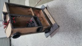
In the picture in post 2 it was not evident that the tiny iso chamber was also ported. This makes things a lot more complicated. This is a high order bandpass, higher than 6th.
The vented iso-chamber is kind of strange. However, the cones of both drivers are also mechanically linked. Given that situation, I'd be curious if it actually makes much of a difference if the chamber is vented. It definitely would if the drivers were not linked together.
A quick way to find out would be to just cover the vent with something solid and to listen for any impact in the bass response. or put a mic at the chamber's vent and record the output when the subwoofer is fed with a pink noise signal.
If you're going to model this in Akabak, the impact of the mass of the mechanical linkage also needs to be taken into consideration. Could get a bit complicated...
When I opened up the center chamber, the roll off went up. And so did the effecientse. I've been wanting to open it up further see pic. That would move away from the traditional band pass and more tward dual vented port.
I'm not going to offer to eat my hat, but l will bet your last name is Lansing, or Meyers. With your understanding of acoustics. I can't thank you enough. And no hurry . Thanks
I'm not going to offer to eat my hat, but l will bet your last name is Lansing, or Meyers. With your understanding of acoustics. I can't thank you enough. And no hurry . Thanks
No loss of bass, just more upper range. Sounded better. Not just kick drum.
What I would expect. the purpose of an iso-chamber is to link to separate drivers together to act as one. By mechanically linking the drivers like you did, you removed the need for such a chamber. You could probably cut the entire chamber out with no change in bass performance.
You may have increased its efficiency at upper frequencies, but I'll bet the response varies all over the map, as the output from that section is basically originating from two drivers that are operating out of phase (as the cone of one driver moves out, the other is moving in). I'd question if it's actually usable. It would look cool though, to see two drivers linked like that, operating in a subwoofer.
Ok, let's break this down into bite size pieces starting with the coupling chamber. This is technically not an iso chamber. An iso chamber is sealed and the reason for that is to provide coupling to two drivers that are not physically attached. In this case you have physically coupled the drivers so there is no need for the sealed chamber at all.
To address the port in the coupling chamber, as far as a sim is concerned it would make no difference at all if this chamber was ported or not. You have two cones moving in the same direction, same speed and they displace the same amount of air. So the net change in air volume in the chamber is theoretically constant, in other words theoretically there would be no air EVER entering or exiting the port and the net pressure and spl coming out of that port would be zero, the two cones provide perfect cancellation.
In real life things are not quite that absolute, air rushes around and some air will be pushed out and sucked in the port but the net result will be negligible and a set of measurements should show that there's no practical difference in having that small coupling chamber ported or sealed. Theoretically you could close it right off and have no difference at all.
So we will totally ignore the coupling chamber.
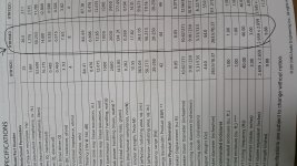
Moving on, we need to find out what the theoretical specs for the drivers are. To add mass (40 grams for the coupling tube or 20 g per driver) and derive new t/s parameters for conjoined driver we will use some of these formulas.
m' = 134.2 grams + 20 grams (per driver) = 154.21 grams
mr = 154.21 / 134.21 = 1.149
Now it's been a long time since I did this and my math skills are rusty but I believe mr^0.5 is the same thing as square root of mr, in that case:
mr^0.5 = square root of 1.149 = 1.072
So the new parameters are:
Fs' = 26.5 / 1.072 = 24.72 hz
Qes' = 0.535 x 1.072 = 0.57352
Qms' = 14.001 x 1.072 = 15.009072
That's all we need to be concerned with, the simulator can do the rest.
To be continued.
To address the port in the coupling chamber, as far as a sim is concerned it would make no difference at all if this chamber was ported or not. You have two cones moving in the same direction, same speed and they displace the same amount of air. So the net change in air volume in the chamber is theoretically constant, in other words theoretically there would be no air EVER entering or exiting the port and the net pressure and spl coming out of that port would be zero, the two cones provide perfect cancellation.
In real life things are not quite that absolute, air rushes around and some air will be pushed out and sucked in the port but the net result will be negligible and a set of measurements should show that there's no practical difference in having that small coupling chamber ported or sealed. Theoretically you could close it right off and have no difference at all.
So we will totally ignore the coupling chamber.
Moving on, we need to find out what the theoretical specs for the drivers are. To add mass (40 grams for the coupling tube or 20 g per driver) and derive new t/s parameters for conjoined driver we will use some of these formulas.
mass(m) = 22.428*dia^4(cm)/(Fs^2*Vas(liters))
m' = m + mass added
mass ratio(mr) = m'/m
Fs' = Fs/mr^0.5
Qes' = Qes*mr^0.5
Qms' = Qms*mr^0.5
then: Qts' = Qes'*Qms'/(Qes'+Qms')
Vas is unchanged
n0 = 9.6352*10^-10*Fs'^3*Vas(liters)/Qes'
SPL = 112.018+10*Log(n0)
m' = 134.2 grams + 20 grams (per driver) = 154.21 grams
mr = 154.21 / 134.21 = 1.149
Now it's been a long time since I did this and my math skills are rusty but I believe mr^0.5 is the same thing as square root of mr, in that case:
mr^0.5 = square root of 1.149 = 1.072
So the new parameters are:
Fs' = 26.5 / 1.072 = 24.72 hz
Qes' = 0.535 x 1.072 = 0.57352
Qms' = 14.001 x 1.072 = 15.009072
That's all we need to be concerned with, the simulator can do the rest.
To be continued.
The vented iso-chamber is kind of strange. However, the cones of both drivers are also mechanically linked. Given that situation, I'd be curious if it actually makes much of a difference if the chamber is vented. It definitely would if the drivers were not linked together.
A quick way to find out would be to just cover the vent with something solid and to listen for any impact in the bass response. or put a mic at the chamber's vent and record the output when the subwoofer is fed with a pink noise signal.
If you're going to model this in Akabak, the impact of the mass of the mechanical linkage also needs to be taken into consideration. Could get a bit complicated...
Yeah, I just woke up when I wrote that and it's inconsequential so I deleted the post. I addressed this part in the post I just added. We can completely ignore the coupling chamber and it doesn't matter if it's closed or ported.
There were a whole bunch of posts posted while I was writing post 14 but Brian is right, theoretically that small coupling chamber could be completely eliminated or it could be sealed or it could be open (with any size opening) and in theory it won't make any practical difference.
As I said though, in real life things are a bit more messy, even though in theory there's perfect cancellation there is air moving and some of it is going to move through the port. Not a lot but a bit. MMD might be a bit different as a result too between open and closed, I'm not totally sure. And even when closely coupled the drivers probably are not in perfect unison. So there will be differences. And those differences will be at high frequencies as Brian said. That chamber is tuned very high.
But as far as a sim is concerned I'm pretty sure it will show there's no difference between removing that chamber completely, or having it there, and not much (if any) difference in having it closed or ported.
I'll finish my quick sim first that ignores the small coupling chamber and then I might do a full on sim in Akabak, but I would need all the box dimensions including the small coupling chamber length width and height.
- Status
- This old topic is closed. If you want to reopen this topic, contact a moderator using the "Report Post" button.
- Home
- Loudspeakers
- Subwoofers
- Id rather be lucky than tallented. Isobaric 6th order band pass