This is VERY preliminary and subject to change. Dimensions won't be correct but internal volumes of chambers are as stated in the drawing. The coupling chamber is completely ignored, it's not here at all. Ports are obviously in the wrong locations but I can't change that in Hornresp, that's a job for Akabak. Drivers are series iso connected and response is shown at 1 watt in reference to the 15.something ohm load.
Check my inputs and math.
3 7/8 inch diameter ports = 76.05 sq cm
6 inch port length = 15.24 cm
If there's any mistakes here let me know now.
I'll update the dimensional info when I get it. But assuming there's no glaring errors here it won't make a lot of difference.
Once I get the properly dimensioned Hornresp sim done I'll export it to Akabak, add the coupling chamber and see what difference that makes. I'm guessing none based on theoretically perfect cancellation.
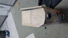
I made it difficult with those angled front panels.
I can't find my angle finder right now. Although the angles were based on platonic solid models from another project.
The way I got the cu. Ft. Is shown in the pictures.
I basically counted the sq.in in one layer then x x h
Sorry for complicating things you will think I should grow up, when you find out the reason for angles
Pics to follow.
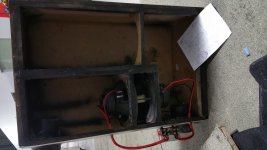
The center chamber makes a considerable improvement in the sound quality. Maybe the nearby ports are interacting interrupting stasis of the cancilation. ?
The port delay phasing with canciled wave
The biggest effect of having that small coupling chamber opened up is that it's going to let high frequencies out. The driver response will extend to very high frequencies and then you have cone breakup and stuff, noise, coming out of that hole.
But as previously stated, the net pressure and therefore net spl is theoretically zero as the volume of air in the chamber is theoretically always exactly the same. Thus theoretically there can't be any resonant output, and theoretically there shouldn't be any high frequencies coming out either. But in the real world you never have perfect cancellation even with physical coupling so any differences will sum to something higher than zero.
One thing you can be sure of is that there's no low bass coming out of the small coupling chamber. Anything that gets out is going to be at the frequency of the helmholtz resonance of the chamber or higher. The low bass should be almost perfectly cancelled out.
A frequency response measurement with the coupling chamber open vs closed would shed a lot of light on what you are hearing.
What crossover frequency and slope are you using with this?
Upon further reflection I don't think there's any way to simulate this exactly as drawn, but I don't think it matters.
I can sim it without a closed coupling chamber just fine (which should be accurate). Or I can sim it without the ducted coupling chamber but without the physical connection between the drivers (this will not be accurate because the bandpass chambers are differently loaded). i don't think there's any way I can set it up to sim both the ducted coupling chamber AND the physical connection between the drivers.
If we have consensus that the small coupling chamber isn't doing anything but letting out high frequency noise that will not impact the simulation in any way I can go ahead with the sim. If not then I can't simulate it.
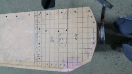
Because of the angles things are more difficult but the important dimensions are cross sectional area and segment length.
The smaller chamber has a length of 18 inches and a volume of 1.385 cu ft, correct? if so I can figure out the cross sectional area from that information.
The larger chamber, the straight section has a length of 34 3/8 inches, a width of 11 3/16 inches and a depth of 12 inches and this section has no angles, correct?
The last part of the larger chamber has 11 3/4 inches and a volume of .808 cu ft, correct? If so I can figure out the cross sectional area for that segment. The end of that segment will have a slight mass loading at the end due to the angled exterior but I really don't want to break that last segment into 3 segments to reflect the exact narrowing as it comes to the end of the segment. The mass loading effect would be pretty negligible anyway.
So can we agree the small coupled chamber does nothing but let out higher frequency noise? And are the dimensions I just listed correct? i'd like to wrap this up.
I can sim it without a closed coupling chamber just fine (which should be accurate). Or I can sim it without the ducted coupling chamber but without the physical connection between the drivers (this will not be accurate because the bandpass chambers are differently loaded). i don't think there's any way I can set it up to sim both the ducted coupling chamber AND the physical connection between the drivers.
If we have consensus that the small coupling chamber isn't doing anything but letting out high frequency noise that will not impact the simulation in any way I can go ahead with the sim. If not then I can't simulate it.
Because of the angles things are more difficult but the important dimensions are cross sectional area and segment length.
The smaller chamber has a length of 18 inches and a volume of 1.385 cu ft, correct? if so I can figure out the cross sectional area from that information.
The larger chamber, the straight section has a length of 34 3/8 inches, a width of 11 3/16 inches and a depth of 12 inches and this section has no angles, correct?
The last part of the larger chamber has 11 3/4 inches and a volume of .808 cu ft, correct? If so I can figure out the cross sectional area for that segment. The end of that segment will have a slight mass loading at the end due to the angled exterior but I really don't want to break that last segment into 3 segments to reflect the exact narrowing as it comes to the end of the segment. The mass loading effect would be pretty negligible anyway.
So can we agree the small coupled chamber does nothing but let out higher frequency noise? And are the dimensions I just listed correct? i'd like to wrap this up.
As I'm looking at the preliminary graph, the segmented spikes represent harmonics?
is that correct? I'm still learning what most of the acronyms in the Thiel measurements represent.
Those big spikes above 200 hz are going to almost completely disappear in real life due to internal box losses. They are extremely narrow so only the wide base of the spikes will remain in a physical measurement.
I'll redo the sim with the correct measurements a when I can. It won't change much, the correct measurements are not that far off from my preliminary sim. If we assume that we can completely delete the coupling chamber in the sim this can be done in Hornresp. The ports won't be in the right spots and I'm not going to account for the angled sides (which only affects a small area of the horn right at the end of the longest chamber) so the sim won't be perfectly accurate but it should be good enough.
Thank You
I will be excited to see the sim when ever you get to it.
with added mass. I would expect it to be lower than 20hz and less efficient?
You probably already know what it will be with all your experience in acoustic modeling. I hope it is unusual so you get something out of it.
I will get some more foam and make a replica of the connector and weigh it.
for correct data.
I like the idea of looking in the center chamber, Don't want to add more mass but if I wrapped the connector with fine coil wire maybe it could drive its own led without wires. I read in Wikipedia you can see sound waves through a parabolic mirror. maybe put one at the back of the chamber. I just cant leave well enough alone.
The added mass was already calculated into the t/s specs in the preliminary sim.
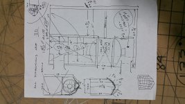
So check my math. The smaller chamber has a length of 18 inches and a volume of 1.385 cu ft. This translates to 38.23 liters and 45.72 cm, input into the Vrc and Lrc input boxes.
The larger chamber, the straight section has a length of 34 3/8 inches, a width of 11 3/16 inches and a depth of 12 inches and this section has no angles. This translates to a cross sectional area of 866.24 sq cm and a volume of 75633.72 cu cm (75.6 liters) input into the Vtc and Atc input boxes. I had to use the throat chamber inputs or I wouldn't have enough segments to complete the sim.
The last part of the large chamber is 11 3/4 inches long and has a volume of .808 cu ft. If this part of the path didn't have angles it would translate to a cross sectional area of 766.5 sq cm and a length of 29.85 cm.
That last part of the large chamber is a problem, as it does angle down towards the port end which will provide a bit of mass loading. But I don't have enough segments in Hornresp to accurately simulate that and it won't make a huge difference.
Both chambers have a port that is 3 7/8 ID and a length of 6 inches. That translates to 76.05 sq cm cross sectional area and 15.24 cm length.
The ports in this sim are not in the right spots, I would have to use other software to simulate their correct positions. It won't make a huge difference though so I'm not sure I should bother.
The coupling chamber is completely omitted in this sim. I did fool around with adding it in Akabak, both with the coupling chamber ported and closed. And since I was not able to physically connect the cones it did make a bit of difference in the sim (since both drivers have a different load presented to them they won't move in identical fashion) so the frequency response was slightly different and there was a bit of output from the port. But theoretically, as we discussed, with the cones physically coupled there should be no pressure changes ever happening in the chamber and no spl coming out of the port. In real life there will be some output since there can never be perfect cancellation, especially with each cone seeing a different load.
So anyway, this sim is definitely not completely accurate but it should be pretty close. As I mentioned, the small changes in dimensions do not make a huge difference compared to the original preliminary sim.
Shown here at 1 watt.
Now let's look at max potential performance.
This is shown at 400 watts total, so power level to reach the 12.65 mm xmax is fairly low. That's good, there won't be loads of power compression. A 25 hz 4th order high pass filter is used here to keep excursion in check below tuning.
But there's a big problem. Both ports are massively undersized, which causes a tremendous velocity speed at xmax. The large chamber port is seeing almost 120 m/s and the small chamber port is almost 90 m/s.
Of course in real life air won't flow through the ports at those speeds, there will be too much resistance, the air will get restricted, port output will decrease for a loss in spl and there will likely be tremendous amounts of audible chuffing. The term for this is port compression.
Ideally you want the velocity to max at 10 m/s to avoid port compression, although audible chuffing won't happen until somewhere between 20 - 40 m/s depending on a few things.
To fix this you can put flares on the ends of the ports but there's a practical limit to how big those flares can be so this will not completely get rid of the problem. The other solution is to make the ports a much larger cross sectional area (ID) but this will require the ports to be longer to maintain the same tuning.
At low power levels I don't doubt that this sub sounds very good, but as far as performance goes, in light of max spl, the fact that you probably are not using a high pass filter, and the enormous port velocity speed at xmax, this enclosure design does not look like it performs well at all at it's limits.
One last thing to look at. You said you were interested in 20 hz, but it appears that this box is 20 db down at 20 hz without a high pass filter, and more than 20 db down with a proper high pass filter in place. You might some room gain making up for a bit of that, maybe even a lot of room gain, but it's hard to make up for 20 db down at 20 hz with just room gain.
If desired you could change the tuning. Using the same 3 7/8 port but lengthening it to 50 cm in the large chamber gives this response, shown at xmax with 225 watts with 18 hz 4th order high pass filter.
Now the response extends down to 20 hz. Max spl isn't as high though since it can't take as much power with the lower tuning. And the velocity, especially in the lower tuned chamber is reduced, partly because it takes much less power to reach xmax. In the large chamber it's reduced by over 2x, from almost 120 m/s to 50 m/s, in the smaller chamber it went from just under 90 m/s to about 67 m/s.
These velocities are still way too high but if you don't use it at max power it might not matter. The big spike at 50 hz isn't ideal either but you could adjust chamber and port dimensions or just eq it.
Lengthening the rear port alone isn't going to make the design perform optimally, but this just gives you something to think about. If you like it how it is now and don't use it very loud then you don't have to change anything. But if you want more performance or lower tuning there are options for you to investigate.
Hope this helps and sorry it took so long to provide this response.
So check my math. The smaller chamber has a length of 18 inches and a volume of 1.385 cu ft. This translates to 38.23 liters and 45.72 cm, input into the Vrc and Lrc input boxes.
The larger chamber, the straight section has a length of 34 3/8 inches, a width of 11 3/16 inches and a depth of 12 inches and this section has no angles. This translates to a cross sectional area of 866.24 sq cm and a volume of 75633.72 cu cm (75.6 liters) input into the Vtc and Atc input boxes. I had to use the throat chamber inputs or I wouldn't have enough segments to complete the sim.
The last part of the large chamber is 11 3/4 inches long and has a volume of .808 cu ft. If this part of the path didn't have angles it would translate to a cross sectional area of 766.5 sq cm and a length of 29.85 cm.
That last part of the large chamber is a problem, as it does angle down towards the port end which will provide a bit of mass loading. But I don't have enough segments in Hornresp to accurately simulate that and it won't make a huge difference.
Both chambers have a port that is 3 7/8 ID and a length of 6 inches. That translates to 76.05 sq cm cross sectional area and 15.24 cm length.
The ports in this sim are not in the right spots, I would have to use other software to simulate their correct positions. It won't make a huge difference though so I'm not sure I should bother.
The coupling chamber is completely omitted in this sim. I did fool around with adding it in Akabak, both with the coupling chamber ported and closed. And since I was not able to physically connect the cones it did make a bit of difference in the sim (since both drivers have a different load presented to them they won't move in identical fashion) so the frequency response was slightly different and there was a bit of output from the port. But theoretically, as we discussed, with the cones physically coupled there should be no pressure changes ever happening in the chamber and no spl coming out of the port. In real life there will be some output since there can never be perfect cancellation, especially with each cone seeing a different load.
So anyway, this sim is definitely not completely accurate but it should be pretty close. As I mentioned, the small changes in dimensions do not make a huge difference compared to the original preliminary sim.
Shown here at 1 watt.
An externally hosted image should be here but it was not working when we last tested it.
Now let's look at max potential performance.
This is shown at 400 watts total, so power level to reach the 12.65 mm xmax is fairly low. That's good, there won't be loads of power compression. A 25 hz 4th order high pass filter is used here to keep excursion in check below tuning.
But there's a big problem. Both ports are massively undersized, which causes a tremendous velocity speed at xmax. The large chamber port is seeing almost 120 m/s and the small chamber port is almost 90 m/s.
An externally hosted image should be here but it was not working when we last tested it.
Of course in real life air won't flow through the ports at those speeds, there will be too much resistance, the air will get restricted, port output will decrease for a loss in spl and there will likely be tremendous amounts of audible chuffing. The term for this is port compression.
Ideally you want the velocity to max at 10 m/s to avoid port compression, although audible chuffing won't happen until somewhere between 20 - 40 m/s depending on a few things.
To fix this you can put flares on the ends of the ports but there's a practical limit to how big those flares can be so this will not completely get rid of the problem. The other solution is to make the ports a much larger cross sectional area (ID) but this will require the ports to be longer to maintain the same tuning.
At low power levels I don't doubt that this sub sounds very good, but as far as performance goes, in light of max spl, the fact that you probably are not using a high pass filter, and the enormous port velocity speed at xmax, this enclosure design does not look like it performs well at all at it's limits.
One last thing to look at. You said you were interested in 20 hz, but it appears that this box is 20 db down at 20 hz without a high pass filter, and more than 20 db down with a proper high pass filter in place. You might some room gain making up for a bit of that, maybe even a lot of room gain, but it's hard to make up for 20 db down at 20 hz with just room gain.
If desired you could change the tuning. Using the same 3 7/8 port but lengthening it to 50 cm in the large chamber gives this response, shown at xmax with 225 watts with 18 hz 4th order high pass filter.
An externally hosted image should be here but it was not working when we last tested it.
Now the response extends down to 20 hz. Max spl isn't as high though since it can't take as much power with the lower tuning. And the velocity, especially in the lower tuned chamber is reduced, partly because it takes much less power to reach xmax. In the large chamber it's reduced by over 2x, from almost 120 m/s to 50 m/s, in the smaller chamber it went from just under 90 m/s to about 67 m/s.
These velocities are still way too high but if you don't use it at max power it might not matter. The big spike at 50 hz isn't ideal either but you could adjust chamber and port dimensions or just eq it.
Lengthening the rear port alone isn't going to make the design perform optimally, but this just gives you something to think about. If you like it how it is now and don't use it very loud then you don't have to change anything. But if you want more performance or lower tuning there are options for you to investigate.
Hope this helps and sorry it took so long to provide this response.
Last edited:
Your analysis is very impressive. and I am fortunate you have helped me. Of course. I will lengthen the larger port to 50 cm. It already has some flare 3/4" half round. Would it help to enlarge the flare, to lets say 3/4" 3/4" round or 2" 3/4 round or more of a conical shape like a vortex? I'm willing to try just about anything. Maybe a 3D printer would work for port ends. If I find a resource, maybe I can have custom port ends fabricated I know many CNC manufacturers. If you would like something to try for yourself or other projects. I will do my best to help. I will send My email address if that is appropriate.
I was messing around I have a 20 foot stick of that 3-7/8" id pipe connected to another box.
I was messing around I have a 20 foot stick of that 3-7/8" id pipe connected to another box.
How much power are you actually sending to the sub? Have you heard any audible chuffing noises? Are you planning on trying to use it at it's maximum potential? Do you care if there are losses if they do not cause an audible problem?
If the answer is no to the last three questions you don't necessarily need to do anything. Roundovers will help with compression and chuffing and bigger is better.
This site is an excellent reference for everything pertaining to flared ports - how to make them out of common plastic pipe or wood, what they do, how big they should be. There's even a small program called Flare It that was derived using empirical test data. His findings were no surprise, compression starts at low velocities, ports should strive to keep velocity at 10 m/s or less and core velocity and chuffing (exit) velocity must both be considered when sizing the port and the flare.
http://www.subwoofer-builder.com/
There's also some highly technical papers on port sizing and flares if you really want to get into measured data. This paper covers a LOT of info, Reynolds number, Moody charts, how to figure out when the port will be overloaded, what turbulence looks like, the effect of dimpled ports (like a golf ball) and a whole bunch of other stuff.
http://koti.kapsi.fi/jahonen/Audio/Papers/AES_PortPaper.pdf
Flares can be either roundover or chamfer up to about 45 degrees, these are the common diy methods since they are easy.
Have you used the fluid dynamics engineering package in solidworks The dynamic visualizations are fun, Real nice 3d CGI stuff. I'm not sure if they have extended the formulas to include sound. They should consult you for future revisions. I have utilized the stress analysis screen shots for structural permits.
- Status
- This old topic is closed. If you want to reopen this topic, contact a moderator using the "Report Post" button.
- Home
- Loudspeakers
- Subwoofers
- Id rather be lucky than tallented. Isobaric 6th order band pass