Well, you don't really need it.
The basic idea is this:
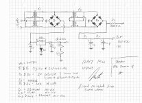
1) the bridge + a 1000 to 4700uF provides unregulated 16 or 17V DC, with, say, something in the order of 1V ripple.
2) the regulator provides *exact* 12.6V or whatever it's set to, and in the bargain ripple goes down to, say, 1 millivolt.
So prefiltering its input is not really necessary.
The basic idea is this:
1) the bridge + a 1000 to 4700uF provides unregulated 16 or 17V DC, with, say, something in the order of 1V ripple.
2) the regulator provides *exact* 12.6V or whatever it's set to, and in the bargain ripple goes down to, say, 1 millivolt.
So prefiltering its input is not really necessary.
To add to this, a cap between adj and ground will knock another 20dB off the ripple and get it to, say, 100uV. It's all in the datasheet.Well, you don't really need it.
The basic idea is this:
1) the bridge + a 1000 to 4700uF provides unregulated 16 or 17V DC, with, say, something in the order of 1V ripple.
2) the regulator provides *exact* 12.6V or whatever it's set to, and in the bargain ripple goes down to, say, 1 millivolt.
So prefiltering its input is not really necessary.
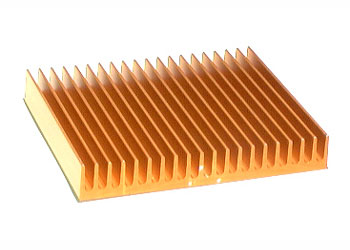
Digikey has a very limited number of heat-sinks, would this be over kill or just the right amount? Newegg.com - Logisys Computer CC8 Copper Heatsinks only I should probably mention its for the LM3876 on a more serious note I was considering this on Ultra U12-40658 Carbon X1 Low Profile CPU Cooler - Intel LGA 775, ITX, MATX, HTPC at TigerDirect.com It's a low profile fan cooled unit for a computer cpu, I assume the fan runs off of 12vdc so I could tap into my heater supply.
Last edited:
Why go with such weird heatsinks?
The first of which, by the way, is a *very* poor design.
I couldn't care less that it's made out of copper if the heat transmission to the fins is through long thin bars.
Yes, it does *look* as if it were the CPU cooler in R2D2's brain , of Star Wars fame.
Go for a good solid classic heatsink, like the one Robert Kesh used successfully.
Agree that Digikey is not very clear as to where to find their heatsinks, I also got steered into the CPU area.
The proper ones are at:
Fans, Thermal Management | Thermal - Heat Sinks | DigiKey
Don't remember what Chip Amp you settled on, but for a 20W class one (TDA2050/LM1875) this one or larger should do:
VHS-95 CUI Inc | 102-1489-ND | DigiKey
For an LM3886 this one or larger:
1963856-1 TE Connectivity | A100339-ND | DigiKey
As a seat_of_the_pants rule, based on experience, 2"x3" or equivalent is enough for 15 to 20W and a 4"x6" for up to 100W.
*Always* with many fins, mounted vertical, and allowing for free air flow, either mounted outside the cabinet or inside but with generous cooling slots.
Unless absolutely necessary, try to avoid fans, one extra complication and what many forget to mention; a source of NOISE.
I mean electromagnetic noise.
FWIW, I use *these* for my 100W Guitar or Bass amps:
5" wide by 2" high, mounted with vertical fins, bolted to the aluminum back panel, so the amp is inside, but the actual fins are outside.
A common solution for MI amps.
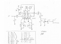
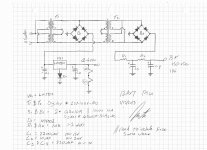
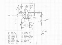
I got every thing finally drawn up and scanned in. If anybody finds any discrepancies let me know, but as far as I know its build-able. I tried to include the parts list on the schematic for everyone. (Edit) I just noticed something on the tube psu C3 & C4 should be rated at a min of 150v not 15v and C2 doesn't need to be 200v more like 20v.
Attachments
Last edited:
")
A couple of things, mostly minor.I got every thing finally drawn up and scanned in. If anybody finds any discrepancies let me know, but as far as I know its build-able. I tried to include the parts list on the schematic for everyone. (Edit) I just noticed something on the tube psu C3 & C4 should be rated at a min of 150v not 15v and C2 doesn't need to be 200v more like 20v.
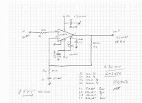
The input of the chip amp is not DC biased to anything after the cap on the output of the tube stage. You can omit that cap (C4 on first schematic) anyway as C3 will block DC and then P1's ground lug will bias your chip amp's input to zero volts. Also, for less components, you could put a 5k pot where R6 is and use that instead of P1.
On a related note, if you build your schematics as separate modules, don't run the chip amp circuit as is. The chip amp needs something between input and ground, don't leave it open circuit, or it may misbehave and damage other components. P1 from the first schematic is what does this normally.
On the chip amp I would parallel C2 and C4 with 0.1uF caps.
Upping C1 so it passes lower frequencies than your input cap is something the hi fi guys recommend. Not sure it's necessary for a guitar, but it does no harm and places less stress on the cap. If you use the current 220k and 0.1uF at input (dropping the 10uF), then I'd use at least a 47uF here, or maybe a 100uF.
A Zobel is also usually used to control high frequency oscillations.
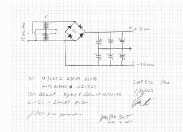
You had a note about fuses. I put three separate fuses on each of B+, chip amp, and heaters. As well as a fuse on the primary side. Maybe that's overkill, but I reckon if one blows it will make tracking down issues much easier, and as each power supply has vastly different current requirements it seems sensible. Remember heater current might be three times what it normally is for the first second or two of warm up.
Also your note about chip amp caps. Chip amps have really good power supply rejection ratio, so you could easily use less than 6. IIRC the original gain card had no caps at all on power supply and just used the caps on the amp's power pins.
You might want to put in some bleeder resistors. You don't want to work on your amp and forget there is 150V in the caps. So put a resistor to ground before R1 (4th schematic). Maybe you want bleeders on the chip amp PSU caps too. 35V or 70V can harm.
Last edited:
I took your advice and replaced R6 with a 5K pot and removed the 10uF cap. C2 and C4 are now paralleled with a 0.1uF cap and also upped C1 to 100uF. Now as far as bleeders go, crunching a few numbers I have determined that on the tube supply I need a 100K @ 0.5 Watt for the 150v. A 10K @ 0.25 Watt for the 12.6v, and on the Lm2876 supply I need two 20K @ 0.25 watt, but the million dollar question is where do I put them. I was under the impression that they run parallel with the last cap in a bank. So on the tube supply should I put it before R1 or after C4? For the record I really appreciate the all the help you guys have been giving me.
What you DO NOT want to do is put the bleeders AFTER any RC resistors in the power supply, as increasing current through them will cause more voltage drop, more ripple, etc. I put them straight after the bridge in my circuits. I have mixed feelings about 100k bleeder for the tube supply. On one hand, you want the caps to drain in a reasonable time, but on the other, it means the bleeder is taking maybe three times as much current as the actual preamp!I took your advice and replaced R6 with a 5K pot and removed the 10uF cap. C2 and C4 are now paralleled with a 0.1uF cap and also upped C1 to 100uF. Now as far as bleeders go, crunching a few numbers I have determined that on the tube supply I need a 100K @ 0.5 Watt for the 150v. A 10K @ 0.25 Watt for the 12.6v, and on the Lm2876 supply I need two 20K @ 0.25 watt, but the million dollar question is where do I put them. I was under the impression that they run parallel with the last cap in a bank. So on the tube supply should I put it before R1 or after C4? For the record I really appreciate the all the help you guys have been giving me.
Don't bother with a bleeder on the 12.6V. The filaments will drain the caps, even through the regulator, and it's low voltage anyway.
The chip amp PSU, just one on each side, paralleled anywhere.
The tubes are drawing way less than that, about 0.3mA each,I see what your saying. 200K - 330K should draw 0.75 mA - 0.4 mA @ 150v (less than tube anode 1.2 mA). I'll post the updated schematics latter today. Again, thanks I don't know how I would have done this without the help of the forum.
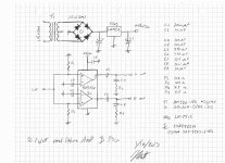
Ok, since the last full-blown post I have made some changes. The biggest change was replacing the 40Watt power section with something smaller. I'm most-likely not going to need all that power. I added the bleeders as told and I'm feeling good about everything so far. let me know what ya guys think. Whoops I just noticed I didn't include the pin-out for the TDA2822, Its almost the same as the data sheet though.
Attachments
Last edited:
Totally depends on how quickly you want the caps to discharge against how much current your psu can cope with.so then 600k-700k?
You probably could put 100k in there, it just seems weird to me for some reason.
Shame you aren't using a big amp. Overdriven tubes sound best at volume.
Last edited:
Your LM7815 regulator won't work.
You have around 16VDC raw DC, plus ripple and all; you can't pull regulated 15VDC from there.
What's wrong with the earlier 40W amp?
The basic idea of hybrid amps such as yours is to "cook and flavor" the sound with tubes, then reamplify it with a clean SS amp, maintaining the original flavor.
A +15VDC powered amp will clip by itself above 5 or 6 W into 8 ohms, so should be used at 1 or 2W.
Suitable only as a bedroom or record-alone-into-PC scenarios.
Forget about rehearsing with other musicians (unless they play acoustic guitars).
- Status
- This old topic is closed. If you want to reopen this topic, contact a moderator using the "Report Post" button.
- Home
- Live Sound
- Instruments and Amps
- Hybrid amp design