CC, am curious about your biasing. What voltages show on the cathodes and grids??
Good point.
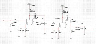
If we make R3 & R6 100k, then we get 0V on the grids with the cathode @ 0.7V and the anode @ ~21V with 0.375mA quiescent, (kind of conventional) but surprisingly with the values shown, the anode moves to ~4V with the cathode and grid @ ~-7.8V, the cathode actually being slightly (about 0.1V) more negative than the grid, the quiescent current goes to ~0.8mA, but the output waveform (when hard driven), while still pretty square, is considerably more symmetrical than with the 100k's (because there's more room to swing positive I guess). When lightly driven, both look quite clean. There's plenty of gain (>35 after both stages) and the FFT looks pretty typical for a tube.
It all kind of blew me away, but I'm not really a tube guy, and I just have to go with the sim. Of course I could be operating it wrong, or there could be problems with the models.
Looking at it again, I'd probably put a blocking cap at the input, it's not hi-fi.
Perhaps you'd care to comment further, as I said, I'm not really a tube guy, I'm just old, old, old.
You do have some valid points. I did remove the 1M resistor, It did make little since after you pointed it out.(pertaining to previous post) I did include a grid stopper (R8, R9, C4), It forms a roll-off at about 4khz. I got rid of the gain at (R4,R2) because it didn't seem like a good idea to load the next stage with 30 volts, but If I can do that without damaging anything I'll remove (R4, R3) and replace with a proper grid stopper. Just to make sure I got my lingo right, a grid stopper is to filter the DC from the signal right? (R10, R11) was to drop everything down to about line level, the pot was just for level control. I do appreciate your provided schematic, but I would hate to just copy your work.
Thanks. Some models aren't good at modelling grid current, which obviously sky rockets when the grid is close to positive.Good point.
If we make R3 & R6 100k, then we get 0V on the grids with the cathode @ 0.7V and the anode @ ~21V with 0.375mA quiescent, (kind of conventional) but surprisingly with the values shown, the anode moves to ~4V with the cathode and grid @ ~-7.8V, the cathode actually being slightly (about 0.1V) more negative than the grid, the quiescent current goes to ~0.8mA, but the output waveform (when hard driven), while still pretty square, is considerably more symmetrical than with the 100k's (because there's more room to swing positive I guess). When lightly driven, both look quite clean. There's plenty of gain (>35 after both stages) and the FFT looks pretty typical for a tube.
It all kind of blew me away, but I'm not really a tube guy, and I just have to go with the sim. Of course I could be operating it wrong, or there could be problems with the models.
Looking at it again, I'd probably put a blocking cap at the input, it's not hi-fi.
Perhaps you'd care to comment further, as I said, I'm not really a tube guy, I'm just old, old, old.
I would hate to just copy your work.
That's the spirit, make your own mistakes.
A grid-stopper is a series resistor placed as close as you can get it to the grid pin on the tube, often ~10k, but the value can actually be calculated to work best with the dynamic input capacitance of the tube.
Grid Stopper Resistor Calculator
No, looks like totally standard two stage design. Even got the standard grid stoppers.Your not yanking my chain right? Thanks, ill post a few pics after I build this thing. Thanks for every ones help.
I guess you may want to be prepared to tweak the output divider to match whatever chip amp circuit you use. And remember you'll need a coupling cap after the output.
If it's of interest, I just built a tube chip amp hybrid myself, just got it working today, but in pieces and bread boards, etc. Two 6N11s and an LM3875.
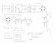
Since everybody been so helpful I was wondering if anybody has an psu advice. I using a Avel Y236652 250VA 25V+25V Toroidal Transformer 122-625 and a 262F6 Hammond Manufacturing | 262F6-ND | DigiKey . I'm 65% sure this will give me what I need With "ok" ripple rejection. I'm most worried about the way I'm going to wire the tube filaments. sorry no neat simulations just pen and graph paper this time.
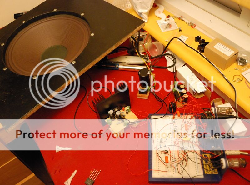
Attachments
Well, here's a pic, but it's far from donevery cool, and I probably will tweak the "attenuator". you should post a few pics when ya get every thing done. I would be very interested to see and maybe hear it.
your +30/-30 is wrongSince everybody been so helpful I was wondering if anybody has an psu advice. I using a Avel Y236652 250VA 25V+25V Toroidal Transformer 122-625 and a 262F6 Hammond Manufacturing | 262F6-ND | DigiKey . I'm 65% sure this will give me what I need With "ok" ripple rejection. I'm most worried about the way I'm going to wire the tube filaments. sorry no neat simulations just pen and graph paper this time.
you have paralleled the secondaries. you either make a centre tap and use 1 bridge, or use two bridges, one for each secondary. And it will probably come out at around +/- 35 or something
You'll find it expensive to get 2200uF caps in 250V. Newark are showing 2, the cheapest is ~U$13. 160V is a bit too close to 150V for comfort, and you won't find those any easier to get. You don't need such big caps anyway. Newark show a 10H 50mA choke for U$8.33. If you don't want to use a choke use a CRC filter. 220uF or smaller will be OK, depending on the current and the exact configuration of CRC filter. If you google it, you'll find a CRC ripple calculator. Or you can use a regulator, but either way you're going to lose some voltage.
If you rectify the heater supply and follow it with a capacitor, you'll get an output DC voltage ~8.9V. This is too much. You need to use an AC heater supply or regulate the DC (or use a dropper, but this will need to dissipate a bit of heat). 9V isn't much overhead over 6.3, so you'll need to be careful with your choice of regulator. It's an instrument amp, you should be OK for hum with AC.
You might need some kind of hum-dinger though, when you join the grounds with an AC filament supply.
I'd be tempted to use a 12V transformer back-to-back with a 9V transformer and run the (DC) heaters in series with an LM317 constant current sink (or source). You'll get 17V rectified from the 12V, this should be enough overhead to run the CCS. From 110V you'll get ~147VAC from the 9V Tx, slightly more from 115V.
Mr. Kesh, love the proto board is that custom? May I ask how you calculated the heat-sink size, Its something I have always wanted to know how to do. Here is my B+ and heater supply. Used MIC29150-12WT Micrel Inc | 576-2206-ND | DigiKey and 2 of these VPP12-800 Triad Magnetics | 237-1054-ND | DigiKey I ran the heaters in series as told (hope It's right) and regulated it for 12vdc. Now the CRC filter seems a bit funny to me. I used the amp-books calc and got a -64.4 ripple rejection. I chose the transformers based an a GE datasheet for the 12ax7. heaters series 12.6v @ 150mA, 150v @ .8mA (per half I think) total current needed is 301.6mA which is less than the max for the transformer in series. Let me know if I missed something, Ill have my chip-amp supply up for approval in a day or so. Thanks in advance.
Attachments
Thanks.Mr. Kesh, love the proto board is that custom? May I ask how you calculated the heat-sink size, Its something I have always wanted to know how to do.
It's a standard bread board from Maplin (UK's equivalent of radio shack) with back panel, that had two holes that were almost the right size for valve bases, so out came the file, and in went the bases.
My hybrid has B+ of 73V (seems ok for ECC88 types in a guitar amp. The idea was to have a single trafo for B+ and chip amp). Not sure how I'd feel about using higher voltages on a bread board.
The heat sink info on the LM3875 datasheet is very thorough, there's a useful table. I followed it, but I think the sink is vastly overrated. The chip stays totally cool, and I haven't even put in any thermal paste yet. Maybe it's because I followed a lot of advice from the chip amp forum about snubbers and decoupling, and maybe it;s because not much below 80Hz is going through it.
One time I left the input not connected, so it was open circuit as the resistor to ground is not on the board (it will be the master volume, and attenuator to line level, as per your schematic). The amp got a little hot, but the zobel resistor, a 400mW, started smoking. Worked ok after, just the paint burning, but I replaced it with a 2W one.
Last edited:
Agreed.You'll find it expensive to get 2200uF caps in 250V. Newark are showing 2, the cheapest is ~U$13. 160V is a bit too close to 150V for comfort, and you won't find those any easier to get. You don't need such big caps anyway. Newark show a 10H 50mA choke for U$8.33. If you don't want to use a choke use a CRC filter. 220uF or smaller will be OK, depending on the current and the exact configuration of CRC filter. If you google it, you'll find a CRC ripple calculator. Or you can use a regulator, but either way you're going to lose some voltage.
I used a CRCRC, but ECC88s are fairly high current. The 12AX7 at 150V with 330k plate resistors will have current in the microamps. You could use some pretty big resistors and lose very little Vs.
Last edited:
")
- Status
- This old topic is closed. If you want to reopen this topic, contact a moderator using the "Report Post" button.
- Home
- Live Sound
- Instruments and Amps
- Hybrid amp design