
")
Based on the 150V supply and 100K plate resistor the load line is something like the red line in the jpg.
If you were designing (close to) symmetrical compression or clipping in that stage then I would think the bias point should be close to 1V.
That would make the cathode resistor 1V / 0.5mA = 2K
And that stage should be able to respond to about 1Vp before the onset of clipping.
Now, how much do you really need to overdrive this stage? 30Vp?
Just a question.
Someone more experienced in guitar amp design should answer that...I would like to know as well.
Attachments
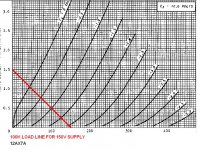
The attenuation is way too much. 300/100300 is an attenuation of 334 times. That load line can swing about +/-55 (less when you consider the AC load line, and even less when you look at what's going on at the cathode, but lets be conservative here) which is about 38V rms and typical line level is 1V rms, though you can set your chip amp up to accept a bit more.
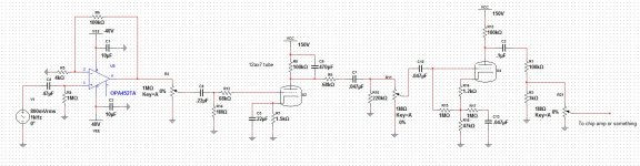
So maybe a 100k and 3k3 would be better. Or maybe 220K and 6K8.
Did you raise the voltage under the second triode to increase clipping?
So maybe a 100k and 3k3 would be better. Or maybe 220K and 6K8.
Did you raise the voltage under the second triode to increase clipping?
Last edited:
Thanks for the feed back. I'm going to look into that right now. May I ask where you learned so much? I need a shove in the right direction.
Look at schematics and read the data sheets...of everything you you can find.
There are many online "learn electronics" things on the internet.
Oh, and the basics are very, very important.
One phrase that keeps popping up is that it takes 10,000 hours to be really good at something.
DO NOT be discouraged by that large number. You can enjoy DIY with much less than that.
Enjoy
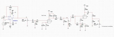
I would suggest that the high voltage op-amp might be better suited in stage 2. From my experience, the real beauty of tube guitar amps is the feel of the input going right into the grid of a tube, so I would like to see a triode in stage 1. You should be able to have enough headroom at +/-40V with that op-amp to fully saturate the next triode stage (stage 3) without over-driving the op-amp.
As for 12VAC on the heaters, you really should have them at 12.6VAC (or 6.3VAC with them in parallel). There is a serious tube life derating if you run the heaters too low, far worse than if you run them a bit too high. You can get small, cheap heater transformers like these ones Hammond Mfg. - Power Transformer - Economical Single Primary - (166 Series)
As for 12VAC on the heaters, you really should have them at 12.6VAC (or 6.3VAC with them in parallel). There is a serious tube life derating if you run the heaters too low, far worse than if you run them a bit too high. You can get small, cheap heater transformers like these ones Hammond Mfg. - Power Transformer - Economical Single Primary - (166 Series)
I mean that 47K, R18. That effectively raises the lowest voltage the anode can swing to by about 50V.Nope, both triodes are at about 150 vdc.
Sir Robert I don't want to sound to needy, but would you by chance happen to have a link on the analytical analysis of a simple triode config. Dozerdave I will rework that tonight and try to post an updated revision. I'm realy glad I decided to join the forum you guys have a lot to offer.
The Valve WizardSir Robert I don't want to sound to needy, but would you by chance happen to have a link on the analytical analysis of a simple triode config. Dozerdave I will rework that tonight and try to post an updated revision. I'm realy glad I decided to join the forum you guys have a lot to offer.
No prob. When you've digested that, go to his homepage and check out the rest of his articles. The one on the DC coupled cathode follower is important, you see it in pretty much every tube amp, is responsible for a good part of tube sound, and is easy to implement in a pre amp.
How to design valve guitar amplifiers
How to design valve guitar amplifiers
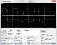
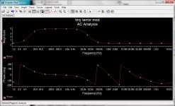
I made a few very minor changes, I ran a frequency response analysis on it and a wave form analysis. I think I'm going to build it when income tax rolls in. If anybody sees anything like seriously wrong with it let me know.
Attachments
- Status
- This old topic is closed. If you want to reopen this topic, contact a moderator using the "Report Post" button.
- Home
- Live Sound
- Instruments and Amps
- Hybrid amp design