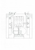
Here is how I would do it. As far as I remember you have a nice fat GND track running along the boards length, I think its safer to use that as GND point. This is the straightforward way to wire your amp, IMO. I did a fast sketch of the actual amp, hope it turned out clear enough. On a further note, take advantage of the chassis height; run the AC along the bottom and the signals near the top. The dotted lines are underneath the board.
I didnt draw all the leads for both channels, in order to keep the drawing clear and easy to understand, the missing leads are just duplicated for the other channel.
Steen")
I didnt draw all the leads for both channels, in order to keep the drawing clear and easy to understand, the missing leads are just duplicated for the other channel.
Steen
Attachments
Nice drawing, thanks!
This is actually quite close to how I would have done it if I hadn't read all Choky's posts about star ground and only one gnd wire to amp board...
Is it correctly understood that only psu wires are grounded on psu board?
Are input and speakers grounded only through wires you have drawn to amp boards?
Any connections to chassis?
Is it normal that the toroids are vibrating slightly? Should I just tighten them?
I have a suspicion that my npn's might be reverse biased as the pnp's were, but I'm unsure what will happen if I try to turn them and it turns out I was wrong...
cviller said:Nice drawing, thanks!
This is actually quite close to how I would have done it if I hadn't read all Choky's posts about star ground and only one gnd wire to amp board...
Is it correctly understood that only psu wires are grounded on psu board?
Are input and speakers grounded only through wires you have drawn to amp boards?
Any connections to chassis?
Is it normal that the toroids are vibrating slightly? Should I just tighten them?
I have a suspicion that my npn's might be reverse biased as the pnp's were, but I'm unsure what will happen if I try to turn them and it turns out I was wrong...
my mate's steen drawing is different than my usual approach in just one detail - spk neg wire ; he route that wire from chanel pcb,and I always route it from central gnd......but-if everything else is OK,both approaches are valid.
looking further at his sketch,I'm sure that steen draw rca jack insulated from chassis ; knowing all his pictures , I know that he always use isolated ones
edit
look at numerous Papa's pictures of First Watt lousy amps..........every one is study of simplicity and engineering approach.
there yo can see what is important and what is mumbo jumbo in all Diyaudio musings
cviller said:Hi Zen Mod, I didn't intend on offending you... I'm just a bit confused because you previously said my wiring was wrong, both with speaker connection and rca connectors, where I used the shield as signal gnd.
I really appreciate you help!
if you can feel anything (of me) just looking at rows of words in this very moment is just weariness and flue ..........I'm really tired.....severall nights with even less sleep than usual,making one lousy site this days......
I didn't even think that I can be offended in any way...
hehe
you are not obliged to live zen in just one path.........
edit
you can do whatever you feel with input RCAs if you keep them isolated from chassis.....in that way you can't make ground loop through shield
Yes, absolutely!.Is it correctly understood that only psu wires are grounded on psu board?
Yes.Are input and speakers grounded only through wires you have drawn to amp boards?
No! We dont have gnd connection through the wall anyways, here in DK.Any connections to chassis?
Yes, they vibrate slightly. If there is DC from the wall outlet, they will be pretty noisy, add a X2 cap if thats the case. They should be fairly tightly mounted.Is it normal that the toroids are vibrating slightly? Should I just tighten them?
There are more than one way of connecting everything, but the way drawn has been pretty good for me. (No hum)
Steen
Edit, yes, isolated RCA's please.
Nope, that takes more than you two Gent'sya see-even steen isn't offended in any way.....
Hope you get well soon, Choky
A big Brandy or two, should take care of the worst symptoms Steen
steenoe said:
Nope, that takes more than you two Gent's
Hope you get well soon, Choky
Steen
hehe
tnx
now I see that I can't see.......even less than usual....4eyes Choky
I talk about RCAs and there are XLRs
anyway
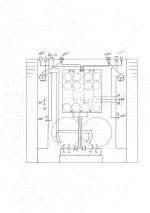
edited Papasteen's sketch,in my usual reinventingboiledwater way
Attachments
Zen Mod said:cviller
slight edit of pic
can you see the difference?
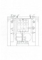
Yes i can. But if you connect the shield to the board you'll have a ground loop. You have turned steen's wiring into the one I have right now... except for the ac line.
Steen, is this the right one? Connected between N and P on ac line before mains?
Attachments
cviller said:
E1........Yes i can. But if you connect the shield to the board you'll have a ground loop. You have turned steen's wiring into the one I have right now... except for the ac line.
E2........Steen, is this the right one? Connected between N and P on ac line before mains?
E1..yes,but you didn't connected shields on both ends,just on input side.....correct?
make AC line as steen suggested
E2......yup,that's one
Excactly rightSteen, is this the right one? Connected between N and P on ac line before mains?
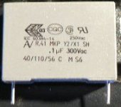
X2 caps are those little critters with all the fancy stamps on them I suggest that you remove both AC connections from your PSU board as the first thing.
Steen
Zen Mod said:
E1..yes,but you didn't connected shields on both ends,just on input side.....correct?
make AC line as steen suggested
E2......yup,that's one
E1: Correct - just like on you stolen sketch. Edit: as the one with input connected to shield - first one I think.
E2: Cool, I'll make space for that when I have to route the ac line anyways.
I always hardwire them directly across the AC-inlet.Cool, I'll make space for that when I have to route the ac line anyways.
Seems like you are under heavy artilleryfire right now. Choky and I have started a Blitzkrieg-campaign
Steen
steenoe said:I always hardwire them directly across the AC-inlet.
Seems like you are under heavy artilleryfire right now. Choky and I have started a Blitzkrieg-campaign
Steen
Yes this is a warzone!

But it's nice to have plenty of ideas to try out with problems like these.
I just double-checked the pnp and npn transistors and it makes no sense to me why mirroring the pnp's should make anything better... perhaps I need to change them back?!
Isn't correct that both bc546 and bc556 have pins c-b-e if you look on them from the top with the flat side facing you?
I'm not dropping the plans on changing my wiring, but I'll wait until tonight.
Isn't correct that both bc546 and bc556 have pins c-b-e if you look on them from the top with the flat side facing you?
I'm not dropping the plans on changing my wiring, but I'll wait until tonight.
Yes they have the same pinout as you describe it.
You can find the datasheets here:
http://www.fairchildsemi.com/
Not many makes the "C" versions of those transistors. 546 is NPN and 556 is PNP, just to make sure.
Just checked your schematic. Q105 in your schematic is not connected as it should be. Compare your sch with Choky's. Choky's is correct and works.
Steen
steenoe said:Just checked your schematic. Q105 in your schematic is not connected as it should be. Compare your sch with Choky's. Choky's is correct and works.
Steen

You might just have found the root cause....
Edit: no, wait q104 is wrong too, so it only explains why I needed to solder them on the other side.
- Status
- This old topic is closed. If you want to reopen this topic, contact a moderator using the "Report Post" button.
- Home
- Amplifiers
- Pass Labs
- Hum problem with jfet Aleph 3 (babbelfish)