cvllier-
I am unclear on one point. Is there no connection from the transformer's secondaries (I assume it is center tapped) to ground at all? or are the secondaries attached to the neutral. When I did that, I got increased hum in my amp.
I know that people often disconnect the earth ground to get rid of hum -- I just don't know if it always works.
Did you check to see if there was any ripple in the signal ground? You can plug your 'scope into an outlet that is on a different circuit than the Babblefish is on, and see what is on the scope. If there is no ripple I would guess that is not the problem, but since you saw 1 mv of ripple on the input shorted to ground -- it has to be coming from somewhere.
JJ
Zen Mod said:leave it for few days; do some other thing,then (we) try again......
Perhaps that would be wise. I just redid the bridges to MUR3020 on a decent heatsink, but no luck there either.

I am unclear on one point. Is there no connection from the transformer's secondaries (I assume it is center tapped) to ground at all? or are the secondaries attached to the neutral. When I did that, I got increased hum in my amp.
I use to bridges and connect center point to gnd on psu.
Did you check to see if there was any ripple in the signal ground? You can plug your 'scope into an outlet that is on a different circuit than the Babblefish is on, and see what is on the scope. If there is no ripple I would guess that is not the problem, but since you saw 1 mv of ripple on the input shorted to ground -- it has to be coming from somewhere.
I have shorted the inputs on the board and I have no signal wire out of the board, so I guess that is not the case. The ripple I saw was on the inverted input of the jfet. It is the feedback signal from output.
Perhaps my negative feedback is not working properly... could that be the case?
Just tried to insert 100k in place of R1 on aleph 30 - not much improvement.
Now I'll take a break to listen and enjoy, cos it sounds marvelous, except for the 100Hz buzz.
I removed two transistors on one channel to see if it was mismatch issue - but it only reduced the buzz because less current was drawn. Now I'm listening to 1.5...
Now I'll take a break to listen and enjoy, cos it sounds marvelous, except for the 100Hz buzz.
I removed two transistors on one channel to see if it was mismatch issue - but it only reduced the buzz because less current was drawn. Now I'm listening to 1.5...
Cviller-
You wrote
"I have shorted the inputs on the board and I have no signal wire out of the board, so I guess that is not the case. The ripple I saw was on the inverted input of the jfet. It is the feedback signal from output.
Perhaps my negative feedback is not working properly... could that be the case?"
The ripple I was looking for here would be caused by an out of phase hookup of your two bridge rectifiers. This possibility is briefly mentioned in the Rod Elliot article I referenced previously.
Having no signal wire out of the board would not matter in this case -- it would be coming through your short to ground. (I am assuming it is shorted to signal ground.)
I think an out of phase hookup would show up at twice the AC mains frequency.
I don't think it would be anything to do with the feedback resistor--it is just a resistor, right?
How did you determine it was coming through the feedback connection?
JJ
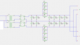
cviller -just try this arrangement where 33K resistor is splited and middle point is filtered via cap;
one thing is still not clear to me;
I tried exact circuit ,same as Steen ( my man ).....without any troubles.............
anyway ........I agree......be sure that secondaries from your two xformers are wired in phase,same as that you wish to make rectifier with just one graetz bridge,with common ground ........
steen....any comment?
one thing is still not clear to me;
I tried exact circuit ,same as Steen ( my man
).....without any troubles.............anyway ........I agree......be sure that secondaries from your two xformers are wired in phase,same as that you wish to make rectifier with just one graetz bridge,with common ground ........
steen....any comment?
cviller said:Steen used insane capacitors - he could filter out a weeks power down...
but I'll changing the phase and try the trick with splitting the 33k tomorrow.
check phase of xformers first ;
that's rule of thumb and common sense that phases in supply must be coherent
it's better to cure culprit.....
anyway- that 33K is connected to minus supply exactly to achieve better CMRR.........comparing to "usual" practice of connecting it to gnd ......it's better like this-at least in my mind
you can also try to put 470n or even 1uF instead 220n there.........later.........when you check phase
check phase of xformers first ;
How can that change much when the input to the bridges are symmetrical? Perhaps I'm missing a vital point here.

Could my problem simply be solved by connecting the secondaries and only use one bridge?
cviller said:
How can that change much when the input to the bridges are symmetrical? Perhaps I'm missing a vital point here.
Could my problem simply be solved by connecting the secondaries and only use one bridge?
read this slowly,same as I'm typing....slowly...... joking ,off course.........
problem is-when you have two independent secondaries in anti-phase - that ripples from both side can be .......how to define this.....in anti-phase too.............so you don't have superposition of plus and minus ripples in your actual load ; instead-you have extraposition of ripples (is that proper word?)
that is the case when you have two bridges ;
in case that you use just one bridge you must connect secondaries in correct phase ,or your supply will be without voltage .........burni,burnie,burnie ............

to be honest- I didn't even think of posibility that secondaries aren't in phase
that's grande no-no .........Hi cviller
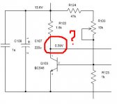
Does 0.39V actually mean 3.9V?
I assume that all components are correctly connected according to the drawing. But, if there is still buzz/hum, I usually suspect two things: instable solder joint (or bolted connect) and ground loop. Where is your star ground?
Does 0.39V actually mean 3.9V?
I assume that all components are correctly connected according to the drawing. But, if there is still buzz/hum, I usually suspect two things: instable solder joint (or bolted connect) and ground loop. Where is your star ground?
Attachments
One other thing to try if you have not already. When I first fired my Aleph up it was dead quiet. Over the first hour or so it started making noises. Humm, buzz, sometimes static noises. I played with everything and checked all of the solder joints. I noticed there was quite a bit of solder flux resin left in certain places on the pcb. I used a small flat blade screwdriver and scraped all of the solder flux resin that was left on the board especially between the pins of the input diff pair(both sides of the pcb).
Then I used a stiff nylon bristle brush on it.
Poof, no more noise! I mean dead quiet...
After that I did some searching and found out that some solder flux is slightly conductive, I never knew that. Maybe mine was!
If you haven't cleaned it off yet then give it a try it only takes a couple of minutes!
Babowana said:Hi cviller
Does 0.39V actually mean 3.9V?
I assume that all components are correctly connected according to the drawing. But, if there is still buzz/hum, I usually suspect two things: instable solder joint (or bolted connect) and ground loop. Where is your star ground?
You're correct, but now it is measuring 4.7V on collector and 0.65V on basis.
I have connected all ground leads to a common point on psu, but that changes nothing. I'm sure it'll make a huge difference when (and if) I mount the whole thing in a chassis.
Chamberman, thanks for your input. I cleand the board, but that didn't help either.
I changed the phases on one of the toriod by changing the primary on that donut, but I didn't observe any changes.
cviller said:I have connected all ground leads to a common point on psu, but that changes nothing. I'm sure it'll make a huge difference when (and if) I mount the whole thing in a chassis.
I believe that you will make that difference in the chassis. But, if there is a real difference, it would come from a difference in ground loop layout, I guess. I have no doubt that you have the common point in PSU. Nevertheless, I often see the hum coming from mis-arrangement of ground loop paths (I don't mean yours). Good luck!
Hi cviller. You are going through the DIY'ers nightmare right now. Dont dispair, it will all turn out to be a happy ending We all went through that worst case scenario, at some point.
Regarding the starground: I have had the best result using the pcb as starground. Check out the ZenV9 layout by PD an Veteran. Choky's Babbelfish layout also provides starground on the board (he just didnt realise it yet ) Running all ground connections to the psu always caused some hum, when I tried it.
The last 3 amps I made used the board as Stargnd, with very good results They are actually very quiet. As an aside, it mostly looks terrible to run all those leads to the psu.
One more thing that makes me a bit worried in your setup is the many secondaries connected together. If one of them has a "cold" connection, that might easily cause the noise. I have a pair of trafo's you can borrow for testing, if you like. You can pick them up, when you come and get the amp chassis I gave you.
Good luck and cheer up, mate
Steen
We all went through that worst case scenario, at some point. Regarding the starground: I have had the best result using the pcb as starground. Check out the ZenV9 layout by PD an Veteran. Choky's Babbelfish layout also provides starground on the board (he just didnt realise it yet
) Running all ground connections to the psu always caused some hum, when I tried it.The last 3 amps I made used the board as Stargnd, with very good results
They are actually very quiet. As an aside, it mostly looks terrible to run all those leads to the psu.One more thing that makes me a bit worried in your setup is the many secondaries connected together. If one of them has a "cold" connection, that might easily cause the noise. I have a pair of trafo's you can borrow for testing, if you like. You can pick them up, when you come and get the amp chassis I gave you.
Good luck and cheer up, mate
Steen
steenoe said:Running all ground connections to the psu always caused some hum
Always? I think you are too definite . . .
steenoe said:Hi cviller. You are going through the DIY'ers nightmare right now. Dont dispair, it will all turn out to be a happy ending
Regarding the starground: I have had the best result using the pcb as starground. Check out the ZenV9 layout by PD an Veteran. Choky's Babbelfish layout also provides starground on the board (he just didnt realise it yet
The last 3 amps I made used the board as Stargnd, with very good results
One more thing that makes me a bit worried in your setup is the many secondaries connected together. If one of them has a "cold" connection, that might easily cause the noise. I have a pair of trafo's you can borrow for testing, if you like. You can pick them up, when you come and get the amp chassis I gave you.
Good luck and cheer up, mate
Steen
steen,my man........
I know that Oly make star looking ground paths on pcb and that's one reason why I (also knowing other pcbs he made ) I always babble how talented is ....hehe
but- if you take a peek at any decent pro specimen of amp (or any other pro gadget) you'll see that you have just 3 gnd wires per channel : one to loudsp output post,one to pcb and one to input XLR ground
in case that you have unbal input,and you use RCA ,you can use shielded cable with shield connected on both sides ( RCA and pcb) ,but only if your RCA jack is isolated from chassis . I know that your connectors are sort of Tiffany , with PTFE rings etc.......

anyway.....let cviller take his amps to your place,call that lousy meister known as Magura ,prepare few sixpacks,and I'm sure that you three will solve problem in vivo..........
ps: on second thought.......let cviller bring sixpacks
edit:
hehe seems that Babo San is with me here

Yep, but since your PSU-stargnd scheme didnt work, he could just as well try minehehe seems that Babo San is with me here
Dont worry, the amp will end up sounding just as great as my Babbelfish And that, for sure, is great indeed.Steen
steenoe said:
Yep, but since your PSU-stargnd scheme didnt work, he could just as well try mine
Steen
yup-world is full with opportunities
anyway- when you try what old farts told you,and that don't work ,then is time for trying other things ......
it's way how things move forward....... and that's good
not (and never) off topic : you and your ppl OK?
Zen Mod said:what old farts told
Old farts like to tell that the star ground can be located at any place as long as the concept and principle of grounding is clearly understood and applied. There is no simple belief that the star ground is to be on PSU or on PCB or on a dot in the inner space of the enclosed chassis
Ask Papa if he is also an old fart

- Status
- This old topic is closed. If you want to reopen this topic, contact a moderator using the "Report Post" button.
- Home
- Amplifiers
- Pass Labs
- Hum problem with jfet Aleph 3 (babbelfish)