Trout said:
Something around 15-20W?
Caddock MP925/930, 25W
MILLS, aluhoused, 50W
Wirewound resistors can vary hugely in quality - you'd think that there would be accepted construction techniques that people could stick to, but there's always yet another way to screw things up in the name of cheapness or expediency.
First off, a lot of the sand-box style resistors use fiberglass cores with end caps simply crimped around the resistance wires. This sort of works, but if you nick the wire with the end cap, or have a nick somewhere along the length of the element, there's a potential failure point. If the end cap is a bit loose, well, there you go....Also, the cheap fiberglass cores have no way of dissipating heat, so one must depend on the cement filler material to dissipate the heat - and hope also that it doesn't react with the hot resistance wire. I only use sand boxes where I want a cheap means of blowing off watts not in the signal path (or not at all).
The premium brands use a nice alumina core as a mandrel for the resistance wire (heat sinking, and the large core provides some surface area for heat dissipation, something not really possible on a skinny fiberglass core). The resistance wires are welded to the end caps - a superior method of termination if done right, a horror if not. I honestly can't say whether a vitreous or a silicone coating is preferable. If the resistors are run properly in an audio context, they shouldn't get hot enough to matter either way. The silicone coating is cheaper.
A rule of thumb for the smaller sizes < 1W is to dissipate no more than 1/2 of the rated wattage (assuming the resistor is sized properly in the first place). If it's the size of a 1/2W resistor it is 1/2W, not 2 or 3 W. For the larger sizes, one must use more derating due to the lower surface to volume ratio. Derate so that the temp for your planned power dissipation and worst case ambient is < 100C, and give the resistor plenty of room.
Moral of the story - stay away from box resistors for critical operations, and derate generously (1/3 the nameplate rating, or maybe less for larger resistors).Try to have the resistor stay below 100C for the planned power dissipation. The resistors can take the heat, but not necessarily the case for adjacent components.
Aluminum cased resistors are nice in that they can be heat sunk, but one must also worry about the voltage isolation and capacitance from the resistance element to the case ( maybe a cathode resistor, but I'd worry about using them for plate loads) . It's best to test both capacitance and voltage isolation when the resistor is heated up from the planned dissipation.
To Trout - what is the power dissipation in your application? I could understand a cheap Xicon opening up, but the Ohmite is another matter, unless it was another box-type resistor.
Running a Pair of 6L6GC's
390 ohm 10W shared resistor
36V across the resistor,
440V measured between the Cathode Pin 8 and anode pin 3
Dissapation around 19W, 43ish ma per tube
The Xiron cement had the lead come loose and pull out of the end after about 4 hours heavy use.
The Vitreous enamel Ohmite went open fairly quickly.
BTW, the ohmite may have been partially defective to begin with. I bought a small box of them from mouser, and had 2 of 12 open right out of the box.
It ran about 25 minutes before intermittently opening.
I suspect I need to get something more along the lines of the Ohmite 270 Series hollow wirewound ceramic resistors around 20 watts maybe more.
Trick is locating the correct value, mouser does not seem to have 390 - 400 ohm in that wattage.
Maybe I can get by with these
Ohmite 20W 400 ohm
Heck...
I just use the green ceramic comp resistors from mouser +/- 10%, I'm sure some of you gasp. I Love em. The only problem is getting all the values one would need. If not I use some of the Dale/vishey military spec ones that start with the RN part number.
I do usually buy X2 what I need and match values, and Parallel/Series them to increase wattage and reduce values.
This is baffling - the derating appears to be ok, so the resistors shouldn't be failing like that unless they're grossly defective to begin with. It's lousy performance even for Xicon cheapo resistors. ~3W for a 10W resistor ain't heavy usage. Out of curiosity, what was the body temperature of the resistor like under those conditions?
The ceramic compostie resistors from Ohmite (are those the ones you mean, athos?) are a good idea for pulsed power handling, but I don't know that I'd trust them to be all that linear. If they're like the Carborundum pulse resistors, they're made of a silicon carbide composite.
The ceramic compostie resistors from Ohmite (are those the ones you mean, athos?) are a good idea for pulsed power handling, but I don't know that I'd trust them to be all that linear. If they're like the Carborundum pulse resistors, they're made of a silicon carbide composite.
Yep thats them, I have them filling most roles in 3 projects, if they degrade the sound of anything then those amps must be lightyears better then the commercial stuff I've bought, to be so degraded and still sound sweet. This is why I've always been sceptical of the absolute difference between parts (like resistors and caps) Whenever something has sounded bad its been faulty construction on my part, not faulty parts. However, I have to say that tube quality, PSU quality (system wise), transformer quality are things that I have heard.
All this being said, I likely have lead ears since I can't understand my wife if the TV is on and I don't mine babies screaming in my ears. And if my RTA is right I don't hear much past 15khz unless its the ringing I hear sometimes in quiet rooms. YMMV bigtime")
All this being said, I likely have lead ears since I can't understand my wife if the TV is on and I don't mine babies screaming in my ears. And if my RTA is right I don't hear much past 15khz unless its the ringing I hear sometimes in quiet rooms. YMMV bigtime
Well, I would want to research exactly what material Ohmite is using in their bulk resistors. Carborundum uses silicon carbide, Ohmite may be using something else. I don't know if it is a bulk material or a sintered composite like a more rugged version of a carbon comp. I've had my eye on them for pulse power circuits, but never entertained the notion of using them in audio.
athos56 said:
All this being said, I likely have lead ears since I can't understand my wife if the TV is on and I don't mine babies screaming in my ears. And if my RTA is right I don't hear much past 15khz unless its the ringing I hear sometimes in quiet rooms. YMMV bigtime
Yup, people know in my past I worked in a recording studio and designed equipment, ask me to come round for my opinion of a new build amp and speaker, "nice to be invited" but suffering from tinnitus isn't a good idea for the signal to noise ratio. A case for for serious aural relaxation therapy. In my age I rely alot on instrumentation.
richy
athos56 said:I likely have lead ears since I can't understand my wife if the TV is on
Can't understand mine with the tv off, but as for resistors...
analog_sa said:
Can't understand mine with the tv off, but as for resistors...
"Can't hear anymore--- been married too long" !
richy
analog_sa said:
Can't understand mine with the tv off, but as for resistors...
the state of the TV has little to do with understanding my wife...
but I think we may have diverged from the original topic
wrenchone said:This is baffling - the derating appears to be ok, so the resistors shouldn't be failing like that unless they're grossly defective to begin with. It's lousy performance even for Xicon cheapo resistors. ~3W for a 10W resistor ain't heavy usage. Out of curiosity, what was the body temperature of the resistor like under those conditions?
The ceramic compostie resistors from Ohmite (are those the ones you mean, athos?) are a good idea for pulsed power handling, but I don't know that I'd trust them to be all that linear. If they're like the Carborundum pulse resistors, they're made of a silicon carbide composite.
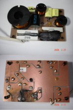
Here is a picture of the 10W 390 ohm Xicon Resistor,
As shown in the photo, the lead is only inserted about 3/32" into the resistor body.
Most of the ceramic dust came out with the lead though some was present before I lifted the resistor for the photo.
As far as heat goes, I still have not gotten and actual temp reading (waiting for more parts).
It does get fairly hot to the touch, Not burn/blister your finger hot, but noticeable.
It does not get hot enough to dis-color the Fiberglass Board Material which is .125 thick Electrical Grade Fiberglass (GP03) with an Operating Temperature Range 0° to +284° F
I mounted it flat and snug to the board, but it had no kinks in the lead nor was it abused in any way.
Picture Below
Xircon 390 ohm 10W
I did some temp checks on an Akane, modern type 3W metal oxide film power resistor, in free air and found the following figures. The max datasheet spec temp for this type is +200°C; (far too high for my liking)
Assume some % tolerance but at; 25°C Tamb,
At rated power 3W, the body temp was 170°C. At 1W derated power the body temp was 70°C. so a 45°C rise.
So if you don't like your resistors stewing at the rated high temp; use 3W types for 1W use. (Note carbon composit types must not run near this, the stability and drift value will be wild).
Interestingly the Radiotron H.b mentions good engineering practice of working round 60% of rated resistor power dissip. This hold fast for the 3W derating to 1W which I measured.
For wirewounds even high temps are tolerated.
It just occurred to me that Morgan Jones mentions something sim.
Obvious; keep those sensitive electrolytic caps well-away from power resistors proximities & heat paths.
I will measure a standard carbon resistor and see what happens.
richy
Trout said:
Here is a picture of the 10W 390 ohm Xicon Resistor,
As shown in the photo, the lead is only inserted about 3/32" into the resistor body.
Most of the ceramic dust came out with the lead though some was present before I lifted the resistor for the photo.
As far as heat goes, I still have not gotten and actual temp reading (waiting for more parts).
It does get fairly hot to the touch, Not burn/blister your finger hot, but noticeable.
It does not get hot enough to dis-color the Fiberglass Board Material which is .125 thick Electrical Grade Fiberglass (GP03) with an Operating Temperature Range 0° to +284° F
I mounted it flat and snug to the board, but it had no kinks in the lead nor was it abused in any way.
Picture Below
Xircon 390 ohm 10W
I bought a bunch of these types, they came in a separate bundle wraped in bubble wrap. I thought , wow these must be fragile, and so I never used them...
Trout said:
Hot resistor in close proximity with 85 degrees electrolytic cap?
That would be a pretty typical failure for a circuit board mounted on a shaker table. Wait, no shaker you say? IMHO, it's just bad construction, probably because cost was the overriding factor. As for temperature, I like my semicons under 160F, but almost any resistor can operate way over that even when derated. The finger test isn't as useful as a good thermocouple reading. Even though the PCB material may be rated for hi temp, I don't like it discoloring over the years. I either keep the temperature lower or mount the resistor off the board somewhat. And certainly away from the caps! There are some flat power resistors from various sources (MEC Holsworthy, Tyco?) that might be useful. They're thick film, but I've used a few 5W parts in parallel with some success. Never had the leads fall off. 
wrenchone said:All this talk about resistors is tempting me to get on my soap box. It is not correct to assume that since there exists a linear relation called ohm's law, that every conductor in every situation will conform strictly to that linear relation. In fact, I consider it somewhat miraculous that enough materials conduct in a sufficiently linear fashion for such a linear relationship to be deduced in the first place.
I apologise for a second reaction to this; I accept all is well-intended, but I find that a bit strong, Wrenchone! I cant shake this feeling that mainstream physics and mainstream engineering is getting in each others way here. I did try to indicate before that physically nothing is perfect (define!) yet a man has been placed on the moon et al, with only 'miraculously conducting materials' - and amplifier electronics are somewhat less intricate.
I would hope that we can take it 'as read' that basics in all branches of engineering should apply at all times. And given that, I simply can't shake this feeling that we going into matters here more of concern to the physicist than in practical electronics. Yet again I would plead for quantisation, which - please pardon me - has been conspicious by its absence in this thread.
Thus I cannot but agree with Wrenchone in principle, but why do we spend all these posts on something that would hardly, if at all, make a difference in practice? (If such was serious, I would have expected to have come across it in my >50 years of R&D in sometimes cutting edge electronics.) This forum is about practical electronics in audio, and if this subject is influential there, it is, with respect, high time that someone now come up with practical figures to that effect.
Wrenchone said:....and hope also that it doesn't react with the hot resistance wire.
Sorry, my friend (not desiring to be knit-picking at your expense) - but that would be new chemistry within the limitations specified for w.w. resistors.
Try to have the resistor stay below 100C for the planned power dissipation. The resistors can take the heat, but not necessarily the case for adjacent components.
It's best to test both capacitance and voltage isolation when the resistor is heated up from the planned dissipation.
Wrenchone,
Here I was again tempted to remark ... but that is common knowledge, ... but I would have been wrong! It is now my turn to say that it is nothing short of amazing how often one finds a 2W resistor cosily packed between two poor electrolytics gasping for air (and subsequently fried after a few years). And I am talking of so-called high-end amplifiers apart from other instruments.
On topic, resistors can have "a sound", from their parasitic effects (incl. tempco). But there is a forum member who stated there is a sound difference due to directionality of your average 0.6W spiralled metal film, inserted in series into a line-level connection.... hell yeah!
- Klaus
- Klaus
- Status
- This old topic is closed. If you want to reopen this topic, contact a moderator using the "Report Post" button.
- Home
- Design & Build
- Parts
- How can a resistor "sound" good?