Yes, I used them on JBL 2384 horns, and they are just cardstock and some titebond. They did seem to help decouple the sound from the speakers, but I didn't do any measurements. I did something similar but with a tapered "bullet" in the middle as a rudimentary phase plug on some others and felt it was even more impactful, but that may not necessarily be a good thing.
Another good material is phenolic perfboard fwiw.
Another good material is phenolic perfboard fwiw.
I must put in my log also that I finally caved in and broke apart my DAC/AMP box, reused the cabinet for an ASP1000 mono amp that Thor struck out last summer and built myself a new power amp. I managed to squeeze in two pcs. of Hypex Nc400 and a "CONNEX SMPS320RxE Power supply board 320W +/-36V" and made my own power splitting cable sets - should be enough for HF duties. So finally the HF is not a problem anymore but it apparently took the heavy guns to make it so. Done deal.
I'm now on the hunt for an other pair of nC400 so if you have a pair unused....")


//
I'm now on the hunt for an other pair of nC400 so if you have a pair unused....
//
I use NCore too. I need it as like you I'm experimenting and need a bulletproof performer and the combination of reliability, load insensitivity, low noise, and highish power is hard to beat in active, changing systems. Right now my NC400s are just on the subs where I need the current into 2, but I might add another pair so each 4 ohm sub pair has a channel. I use 2x Buckeye Amps build of 6ch NC250 for everything else in the active HT (well, LCR are active 4 and 3 ways, surrounds are just "normal" systems I had on hand that fit the space.
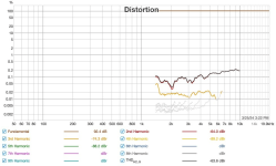
Why did you stop the HF measurement when the driver needs to play through past that point? What really matters most is likely the combined measurement but the Thd through the crossband is always interesting to see separately. I am interested to see if you are following through. Also if 90db is your max intended average, what does thd look like at +15db above that, interested to see if this system is transient accurate for that level or if a lower average is needed for accurate playback. To be clear, take separate, complete, measurements of each driver at average and peak levels.Distortion at calibrated levels:
View attachment 1290551
Measurement setup: 70cm to WG mouth.
Low frequency levels are not surprising given that there is 4 pcs of 4" woofers in a too small closed box playing
View attachment 1290545
View attachment 1290542
Just to verify that it is not the HF part that is contributing
View attachment 1290544
View attachment 1290543
200 and up looks quite good ;-) but would lie to see 1k region drop to 0,1% ...
//
Last edited:
Because when level is dropping from a XO, distortion measurement gets uncertain. The little SB driver has unfortunately this increasing distortion around 1k when level is rising. The analysis and cause for it is known. I play at 70-80 peek so no need. The system was never specified to play loud. I'm good.
"...following through"... ?
//
"...following through"... ?
//
Last edited:
Yes follow through. In analysis of my crossover point, you were pointing out Thd that were -10db or more deep in the crossover... I thought it peculiar you did not subject yourself to the same expectations, You make excuses; "Because when level is dropping from a XO, distortion measurement gets uncertain." and hide your results from the thread. Your thd measure stops almost a half octave before the xo point and Thd is obviously starting to peak. I wonder how high thd gets on your tweeter through the crossover, and find it interesting you do no hold yourself to the same standards that you strictly implied to my crossover.Because when level is dropping from a XO, distortion measurement gets uncertain. The little SB driver has unfortunately this increasing distortion around 1k when level is rising. The analysis and cause for it is known. I play at 70-80 peek so no need. The system was never specified to play loud. I'm good.
"...following through"... ?
//
Attachments
@TNT I was referring to your post above about low SPL use because the SB doesn't like to give level at 1k. I'm not sure I could live with that limit in the back of my mind. Kind of like lowthers etc in that regard, can be exceptional but have major limits around output. Always a compromise eh?
Hi, regarding HF distortion on your previous post, was that measured with 16ohm series resistor, opening post mentions it? if it is, try adding one high pass filter pole with inductor between resistor and the driver, parallel to the driver. This enables the driver to dampen itself at resonance, which should reduce that ~1kHz distortion hump. That's the fundamental resonance for NDS1095 according to datasheet, and a series resistor would reduce electrical damping, which allows the driver to resonate more, great excursion (also acoustic output of course), but the excursion distorts the whole bandwidth. Undamped resonance could likely react to external excitation as well, like sound from the woofers earphoned by the waveguide. I think electrical damping on compression driver resonance would really help with sound. You might find out the frequency response doesn't work with your plan now, but you'd be able to evaluate if it does and does the distortion matter there and so on.
Here some quick measurements of my hf10ak driver, the other is with series capacitor and L-pad, and the other is series resistor and parallel inductor like described. I've got DSP to manipulate frequency response, but that was not used on these quick measurements so are not matched.
Was just a quick check if there was any difference, and it seems so. If you have time try it out and see if there is difference with yours.


Lowest resonance for this driver is around ~600Hz, and series capacitor and L-pad really reduce electrical damping visible as peak in frequency response as well as in distortion hump (2nd order!). At least that's my analysis with this quick test I did sometime last year, and why I think your's would reduce too. You could do a quick test without the series resistor (or cap or anything betwee namp and driver). https://faitalpro.com/en/products/HF_Drivers/product_details/index.php?id=502010110
Here some quick measurements of my hf10ak driver, the other is with series capacitor and L-pad, and the other is series resistor and parallel inductor like described. I've got DSP to manipulate frequency response, but that was not used on these quick measurements so are not matched.
Was just a quick check if there was any difference, and it seems so. If you have time try it out and see if there is difference with yours.
Lowest resonance for this driver is around ~600Hz, and series capacitor and L-pad really reduce electrical damping visible as peak in frequency response as well as in distortion hump (2nd order!). At least that's my analysis with this quick test I did sometime last year, and why I think your's would reduce too. You could do a quick test without the series resistor (or cap or anything betwee namp and driver). https://faitalpro.com/en/products/HF_Drivers/product_details/index.php?id=502010110
Last edited:
Looking at those measurements, are you certain that it is just the Sb at fault? Your tweeter measurement isn't far off from the combined thd measure. What does the 4" look like measured alone. This is all just for exercise, since you can't relate these to perception, and you probably have plenty of headroom.
Hi!
It was with an 8 ohm resistor - I have abandoned the initial idea for HF amplification . Whats your recommendation for an R?
And how to calculate a suitable L used the way you describe - I'd be willing to test this.
The measurements you show - are these calibrated at 1 meter? If so, very good.
//
You could load your data to vituixcad, impedance and frequency response, then play with simulation. You could check series impedance with the driver as well, try to minimize it around 1kHz. Adjust the R as you like, the 8ohm for example for suitable attenuation. The coil should be low ohm air core, adjust inductance so it makes plausible crossover which you can refine still with DSP. I really don't remember what mine are, need to pop up vituixcad later and check it out.
Unfortunately the measurements are not calibrated, just some quick dirty experiments to see relative difference. I must do these again some day, take sound samples and so on, perhaps even try to calibrate somehow It would be fun to use the compression driver as microphone, and listen what the woofer sounds like
Unfortunately the measurements are not calibrated, just some quick dirty experiments to see relative difference. I must do these again some day, take sound samples and so on, perhaps even try to calibrate somehow
It would be fun to use the compression driver as microphone, and listen what the woofer sounds like Meanwhile, found my old post with screenshots as an example https://www.diyaudio.com/community/...ities-of-hybrid-crossover.389129/post-7093812
...have to ask... I don't think I had a site year 2000 - sure you are not mixing me up with someone else?Interesting. I couldn't safely use the power on tap and retain my hearing here but I don't know that I could live with that low a ceiling. BTW, your site was one of the early influences when I got into DIY back in y2k. Thank you.
//
- Home
- Loudspeakers
- Multi-Way
- Hornflower 2-way point source