Ok, so, if I was to make in to a back firing design, then I would have back wall reinforcement. Ok, I can deal with this though. Besides, I have achieved the goal I set out with thus far. I wanted a small enclosure that will allow me to use my FE126E drivers that are just collecting dust, I wanted it to be a compact enclosure (but not overly compact so as to require corners). And I wanted a new speaker project. Besides, I am just dead curious to build this thing. Aside from the silly overlook of the SD which was a first, I think from the look of the plot I am pleased. I believe I will build it. I will send the plans your way Scott. I need to see if I can dig up your email address. If not I will let you know.
Tom
Tom
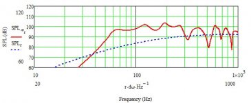
Scottmoose said:At the risk of sounding pedantic, I think you'll find the cut-off is 70Hz... graph-scale starts at 10Hz, not 0. For a driver with a 90Hz Fs, a fairly small cabinet & only the floor boundary condition to increase terminus size, that's not too bad a result at all, especially with a fairly smooth FR.
If you want to go lower, I'm afraid you're going to either have to go larger & longer, or use greater boundary reinforcement (rear wall + floor and / or corners).
Thinking over the last few hours has spawned some questions. The original intent of this thread was to figure out how to get the T/L action right so that I could reach 50 Hz in a small enclosure. I seem to have hit 70Hz, fairly smoothly and cleanly. Now, with my length being 70, shouldn't the 1/4 wave kick in and give me something along the lines of 50Hz or should my flair be set to 100 Hz and my length me attenuated so that the 1/4 wave is predominant at 50 Hz? This is where I am still confused. Any help from any one is always appreciated. Thanks!
Tom
Harderror said:I was entering the SD wrong.
Greets!
I have a cure, 'save as' the WS as something else, then highlight the input field and type in 64*cm^2 and from now on you can just highlight/input the Sd.
GM
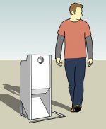
Unfortunately I am stuck with Explorer. So, everytime I do a sim I have to re-enter all the data. Man I wish I could save my sheets! Every single time I change all my units and enter all the data, EVERY SINGLE TIME! I wish I could find a copy of Mathcad cheap, or if anyone isn't using their's anymore free! hehe Here is a relational image of the final enclosure. I managed to lower the cutoff a bit to ~67-65. Man, I am excited to build this thing.
Tom
Tom
Attachments
Harderror said:Unfortunately I am stuck with Explorer. So, everytime I do a sim I have to re-enter all the data. Man I wish I could save my sheets!
Explorer?!
Anyway, when I was using the V8 demo on MJK's site I saved each sim I wanted in WORD, made changes, etc., keeping V8 running all the time. Also, any section not security locked can be copy/pasted into WORD and I assume similar type WSs.
GM
Harderror said:
Thinking over the last few hours has spawned some questions.
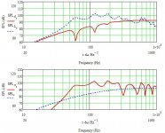
Hmm, 50 Hz horn in small Vb = no bass unless it's a DSL style tapped horn with the right driver. The sum total axial length must = the desired acoustic 1/4 WL = the flare frequency and since a BLH is a 4th order alignment, then the horn's cut-off (F12) is a half octave below the desired gain BW, or 0.707*50 Hz = 35.35 Hz in your case.
BTW, why is your Fh > the driver's mass corner F? I mean how is it going to sum ~flat through the acoustic XO BW?
A quicky sim ignoring end correction using the measured specs:
GM
Attachments
GM said:
Hmm, 50 Hz horn in small Vb = no bass unless it's a DSL style tapped horn with the right driver. The sum total axial length must = the desired acoustic 1/4 WL = the flare frequency and since a BLH is a 4th order alignment, then the horn's cut-off (F12) is a half octave below the desired gain BW, or 0.707*50 Hz = 35.35 Hz in your case.
BTW, why is your Fh > the driver's mass corner F? I mean how is it going to sum ~flat through the acoustic XO BW?
A quicky sim ignoring end correction using the measured specs:
GM
I am not sure I get what you mean. Maybe if you could expand upon what you are saying? How is my Fh greater than my Mass corner F? In addition, are you saying about my flare that I should have calculated the flare as a 35.35 Hz flare and then what do I do with the length?
AndrewT said:Hi,
I read GM's advice and got a bit confused as well.
I approach slightly differently.
Design the flare rate to suit the lowest frequency/(sqrt2) = 50/1.4 = 35Hz.
Design the mouth area and the minimum length to suit the lowest frequency = 50Hz.
I guess I still wonder how this is going to activate the T/L action. I could be wrong but isn't the length to the 1/4 wave of 50 Hz key here? From what you are saying I don't see that being taken into account. I of course am learning all of this as I go. Thanks!
Well, looking at GM's points in turn, the tapped horn is Tom Danley's double-tapped design for sub-bass production. Without resorting to massive Eq, as GM mentions, this is about the only way to get high LF gain out of a small Vb. Not something for FR units though -strictly sub-bass & bass horn duties only.
Axial path-length (assuming you're using 1/4 wavelength rather than the ideal minimum 1/2 wavelength tuning) wants to be 1/4 acoustic wavelength of the desired tuning. A BLH is really just a 4th order BP alignment (as I mentioned earlier, most back-loaded horns are basically reflex boxes with gigantic vents which provide the majority of the gain BW). So final cut-off is taken as approx 1/2 octave below tuning, or 0.707 the selected tuning frequency.
The Fh being greater than mass-corner point, was a reference to your data entry error that I mentioned before in re driver Sd. Not something you need to worry about now you know how to do it.
You don't activate QW action per se. Well, you do, but it's a consequence of reducing the cabinet size / Vb over the ideal where minimum pathlength = 1/2 acoustic wavelength of the LF cut-off & mouth circumference = 1 wavelength of the same. Below this point, the box is acoustically too small for horn loading, so you're actually using mainly QW action until, as frequency rises, it blends into horn loading as the mouthsize & pathlength become large enough for the cabinet to function as a horn again. One of the benefits of rear-wall / corner-loading of course is that because you're increasing the size of the mouth by a factor of 4 / 8, you're maintaining horn loading down to a lower frequency.
AndrewT said:Hi,
I read GM's advice and got a bit confused as well.
I approach slightly differently.
Design the flare rate to suit the lowest frequency/(sqrt2) = 50/1.4 = 35Hz.
Design the mouth area and the minimum length to suit the lowest frequency = 50Hz.
Greets!
?? How is it any different other than I used the reciprocal of SQRT(2) and explained why it's used? If you mean only make it 50 Hz long instead of ~35 Hz, it will only load to ~70 Hz in half space, making it in my mind a ~70 Hz horn.
GM
Hello,
think about the real and blind part of a "horn",
take a flare rate 1 oktave below the wished lowest frequence,
open the last meter with double flare rate, but
normaly you will get for 1 W 1m a needed membran movement
at ~70 Hz ~1 mm and around 100-150 Hz o,6 mm, (TUBA)
so take the right driver to get min. 2 W impuls.
In my double horns you can use Xmax 0,6, because you take
two and 2 different horns, it linearized the movement.
Scottmoose said:
The Fh being greater than mass-corner point, was a reference to your data entry error that I mentioned before in re driver Sd. Not something you need to worry about now you know how to do it.
You don't activate QW action per se. Well, you do, but it's a consequence of reducing the cabinet size / Vb over the ideal where minimum pathlength = 1/2 acoustic wavelength of the LF cut-off & mouth circumference = 1 wavelength of the same. Below this point, the box is acoustically too small for horn loading, so you're actually using mainly QW action until, as frequency rises, it blends into horn loading as the mouthsize & pathlength become large enough for the cabinet to function as a horn again.
Greets!
?? I was referring to the horn's HF roll-off Vs the driver's transition to its mass controlled BW, i.e. Fhm = 2*Fs/Qts. Tom's horn sim rolls off at a higher Fhm. Typically you want the horn's response -3 dB at this point.
?? Horns have a 1/4 WL fundamental, so it's always there except in the theoretical infinite horn and once it's acoustically a 1/2 WL long it will be 'on the pipe' (as 2-stroke racers say) over some BW no matter what the box/mouth size is, so like a BR's gradual transition to MLTL, so goes a horn's transition from 1/4 - 1/2 WL loading. Of course if it's too short to support 1/2 WL loading in the desired passband, then it will be too low in amplitude to be more than out of BW 'noise' comb filtering with the driver's output that needs to be damped down for best performance.
GM
Oh dear, this is what's happening to me these days. I'm not reading anything carefully enough. Too much time spent on cruisers, not enough on audio.  Sorry about that Greg & for any confusion caused.
Up side, the second was in fact what I was trying to clumsily put across (thanks for the clarification.") ) so at least I haven't entirely lost it. Yet.
) so at least I haven't entirely lost it. Yet. 
Sorry about that Greg & for any confusion caused. Up side, the second was in fact what I was trying to clumsily put across (thanks for the clarification.
) so at least I haven't entirely lost it. Yet. GM said:
Greets!
?? I was referring to the horn's HF roll-off Vs the driver's transition to its mass controlled BW, i.e. Fhm = 2*Fs/Qts. Tom's horn sim rolls off at a higher Fhm. Typically you want the horn's response -3 dB at this point.
?? Horns have a 1/4 WL fundamental, so it's always there except in the theoretical infinite horn and once it's acoustically a 1/2 WL long it will be 'on the pipe' (as 2-stroke racers say) over some BW no matter what the box/mouth size is, so like a BR's gradual transition to MLTL, so goes a horn's transition from 1/4 - 1/2 WL loading. Of course if it's too short to support 1/2 WL loading in the desired passband, then it will be too low in amplitude to be more than out of BW 'noise' comb filtering with the driver's output that needs to be damped down for best performance.
GM
Well, my fhm would be around 500 Hz no? So, I would want a larger CC to account for this? Ah, my mathcad problems are solved (referring to what we were discussing earlier). Life is good. Mathcad 14 is good. I can run it on my Vista box. Ok, I have had some luck with getting the horn lower without any serious modification to the base plan as well. I am going to play with the mouth flare rate today to see if I can bring the shelf up to +6 db instead of 4 at 58 Hz. I have come to the end of how long I want to make the horn though. I don't want to make the enclosure any taller so... The flare is where I can do more.
Attachments
Harderror said:
Well, my fhm would be around 500 Hz no? So, I would want a larger CC to account for this?
Greets!
Correct.
GM
- Status
- This old topic is closed. If you want to reopen this topic, contact a moderator using the "Report Post" button.
- Home
- Loudspeakers
- Full Range
- Horn/Transmission line help