Scott, I have been playing with the smoothing of the terminus and I am just confused. What I have showed as well as what I have come up with since don't seem to smooth much at all. It just seems to ease the severity of the bend. Maybe you could give me an idea of what you were thinking with an example of some sort? I think I am obsessing over nothing here but like Ron said, I live for the challenge.

Tom
Tom
Harderror said:Scott, I have been playing with the smoothing of the terminus and I am just confused. What I have showed as well as what I have come up with since don't seem to smooth much at all. It just seems to ease the severity of the bend. Maybe you could give me an idea of what you were thinking with an example of some sort? I think I am obsessing over nothing here but like Ron said, I live for the challenge.
Tom
As I mentioned & Martin noted above, the existing MathCAD worksheets (good as they unquestionably are) can't model the effects of end correction very effectively. That's why you're not seeing any real changes in the simulated response. Martin's slowly working on this, & some other things at the moment for upgrades to future itterations of the worksheets.
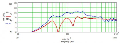
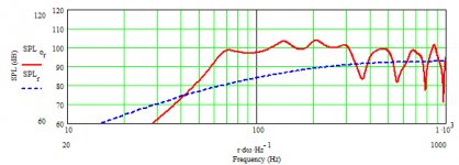
Ok, I have modified the line fully and I amvery pleased with the result. I know what you said about Martin's worksheets but I am a bit worried about the T/L swings I am getting from 350Hz on up. I also (according to the sheet) have a 10 DB drop on the slope from 100-50Hz. Overall the plot looks good and I believe this would be a nice sounding enclosure built right from these final plans but I was thinking about what I could do better before I do the build. Any thoughts? Scott? Ron? Martin?
Tom
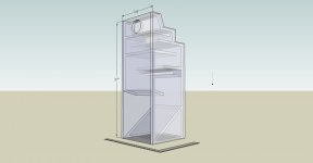
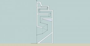
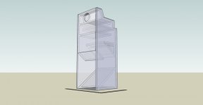
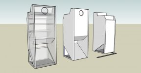
Attached are the images of the enclosure cross section as it is now and the plots from mathcad.
Tom
Attached are the images of the enclosure cross section as it is now and the plots from mathcad.
An externally hosted image should be here but it was not working when we last tested it.
An externally hosted image should be here but it was not working when we last tested it.
An externally hosted image should be here but it was not working when we last tested it.
Well, she is ready to build then. I will finish drawing up the plans if anyone is interested. I will probably build in a couple of weeks. The semester starts this week so I have to deal with students. Maybe I will start a seperate thread dealing with the build and testing if enough people are interested.
Tom
Tom
It'd be interesting to see your plans at some point.
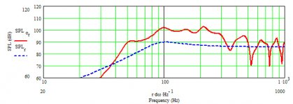
One thing that occurs to me, now I've looked at the plots in greater detail. See the attached horn with the 126 -ignore the red line & compare the blue driver IB curve to your own. Are you adding series resistance to yours? Or are you sure you've got the driver parameters entered in right?
One thing that occurs to me, now I've looked at the plots in greater detail. See the attached horn with the 126 -ignore the red line & compare the blue driver IB curve to your own. Are you adding series resistance to yours? Or are you sure you've got the driver parameters entered in right?
Attachments
Scottmoose said:It'd be interesting to see your plans at some point.
One thing that occurs to me, now I've looked at the plots in greater detail. See the attached horn with the 126 -ignore the red line & compare the blue driver IB curve to your own. Are you adding series resistance to yours? Or are you sure you've got the driver parameters entered in right?
No, no series resistance. Shoot, I am not sure where that is coming from. I am using the ts parameters you suggested but I checked them and they look ok. Hmm let me play and we will see. Here is the cabinet in its final form.
Tom
Attachments
At the risk of sounding pedantic, I think you'll find the cut-off is 70Hz... graph-scale starts at 10Hz, not 0. For a driver with a 90Hz Fs, a fairly small cabinet & only the floor boundary condition to increase terminus size, that's not too bad a result at all, especially with a fairly smooth FR.
If you want to go lower, I'm afraid you're going to either have to go larger & longer, or use greater boundary reinforcement (rear wall + floor and / or corners).
If you want to go lower, I'm afraid you're going to either have to go larger & longer, or use greater boundary reinforcement (rear wall + floor and / or corners).
- Status
- This old topic is closed. If you want to reopen this topic, contact a moderator using the "Report Post" button.
- Home
- Loudspeakers
- Full Range
- Horn/Transmission line help