Your point doesn't fall on deaf ears Ron. I appreciate your honesty and I have enjoyed your input as well as designs over the last few years. The further I move within this wondrous hobby of ours the more I realize I don't know, and the more I desire the information. As a result of this, I know more about math than I ever thought I would in this life. It makes me happy though. That is what counts.
Tom
Tom
Harderror said:I will say though, the design I shared with you ended up blowing everyone away that has heard them. They are my primary pair now with a pair of 300b SETs (that I built) driving them.
I must have missed the discussion of your design or maybe I have forgotten, can you bring me back up to speed on what you built.
I truly am blown away by Martin's work. I wouldn't be anywhere close to where I am without him.
Thanks, glad you found it useful. I am back working on horns again and have some more to add to my theory page. I think that my modeling of the mouth and surrounding baffle/edges is going to improve significantly and some new improvements to the worksheets will result. Progress is slow but steady (I keep being attracted back to OB designs, maybe I have to consider another write up on active crossover designs).
Scottmoose said:I don't think the 126 is not going to do it mate. Not properly. You pick the tool you need to do the job, and if you're into big classical pieces, at high sound pressure levels, the 126 isn't exactly the unit that springs to mind -it's not quite blood out of a stone, but not far off. Something larger would be preferable & make your own task considerably easier.
Martin's paper is an excellent starting point for people new to horns, but it doesn't cover everything (such as hyperbolic / hypex / conical etc flares), & there are other works out there that will allow better optimisation to a specific drive-unit. Don't get me wrong, I'm not saying don't use it (far from it), just keep in mind that there are other papers too which can be used in combination with it. The heavy artillery are WML, Tom Danley & Earl Geddes. (Ron too I might add, but he hasn't published any papers on the subject AFAIK)
Of particular significance is WML's On the Specifications of Moving Coil Drivers, if you haven't already read it. The math will give you a major headache, but it's worth persevering with it. The equations are set so as to allow you to extract the maximum possible efficiency out of a driver -this has its downsides, but high-gain is usually preferable: just damp what you don't need. You can also download the nifty little programme MLUtil, based on these equations. It's worth still doing some manual work with them though so you can set appropriate upper & lower corner frequencies. The programme with then churn out dimensions which you can then enter into MathCAD & play with. Nice little bit of software & one I use quite a lot. Note these are still based upon the 1 dimensional wave equation (Rayleigh, Webbster etc) which are fine as far as it goes, but, as Earl & Ron point out(and Voigt, to be fair -think of the tractrix), this isn't everything. Wavefronts are not plane.
As I noted above, boundary reinforcement is your friend. If you can corner-load, then so much the better.
Remember, ripple in the frequency response of a compromised horn is caused principally by the terminus size not being large enough (i.e. the horn is acoustically small compared to the wavelengths it's trying to reproduce. The result is a standing wave (supersonic shockwave) which is reflected back from the terminus along the horn-path. The air-cavity behind the driver (we're assuming a typical BLH here) can't filter all of this off, and it modulates the driver, causing the ripples in the response.
There are a few things you can do about this. You can cram it full of damping (not a good idea: microdynamics vanish) make a large back-chamber (won't support the cone as well, so excursion increases & distortion at high SPLs rises. I'll come back to this in a minute though), or use the folding scheme to help. The main problem occurs at higher frequencies, right? A modestly sixed air-cavilty can't get all of them. However, HF hates bends with a passion. Short wavelengths. So, if you introduce a couple of bends near (but not too near) the throat, you will naturally filter off these, leaving only the LF to pass though (longer wavelengths aren't worried about the bends, so long as you don't go crazy & make something that looks like a python with heartburn.
Whatever you do, make sure the minimum length of your horn is 1/4 your target cut-off. For 50Hz, that's roughly 68in (depends on local speed of sound). Ideally, for maximum performance, 1/2 wavelength or greater is needed.
Oh yes: one last thought. (Chambered) back loaded horns = very small bass reflex cabinets with very large vents.
Thank you Scott. What you are talking about above fits well within what I have done with this enclosure. It won't be corner loaded but then it is 14x14x37. almost four times the Frugal's size. I will begin reading the above and see what else I can glean. The bend at the terminus I discovered by mistake. I needed to fit some bends into a limited area that I had left to work with so I put a short run with a bend. Voila! Nare a problem with HF at the mouth. I know it didn't solve the problem entirely but it was a contribution. Thanks to all of you for your support. If anyone has anything to add (that is helpful) please by all means. I need all I can get.
")
Tom
MJK said:
I must have missed the discussion of your design or maybe I have forgotten, can you bring me back up to speed on what you built.
Thanks, glad you found it useful. I am back working on horns again and have some more to add to my theory page. I think that my modeling of the mouth and surrounding baffle/edges is going to improve significantly and some new improvements to the worksheets will result. Progress is slow but steady (I keep being attracted back to OB designs, maybe I have to consider another write up on active crossover designs).
Martin, my design was never fully posted on here or anywhere as I for whatever reason was thinking of working towards commercialism. Ugh. hehe But here is the thread http://www.diyaudio.com/forums/showthread.php?s=&threadid=96217 and as soon as I can I will try to draw up some solid plans to share. One other thing MArtin, I apologize for not paying my dues this year yet. I am a bit late. As a professor, I don't get paid until mid feb. at which point I will buy this next year.
I totally understand wanting to come up with your own design, to me it is kind of the goal if you make diy audio a hobby. If you just want to build a good set of speakers then that is easy, anybody can do it with how good the plans are on frugel-hornif they have a garage and some tools. But if you want to have something to really be proud of then your own design is best. My wife mentioned selling speakers at a local art fair we have every year in my home town, I do not think it would work but I can not get the idea out of my head, and I would feel kind of guilty just ripping off what Scotmoose and Dave has done. We will see if I ever invest the time in learning the required math since math does not come natural to me at all. Too many hobies and not enough time.
I am really glad I have built what I have, my stereo sounds way better than anything I would have been able to afford comercially. I am very gratefull for the frugel-horn site and all the work they do to make it, and do not want to sound like I am not.
Ed Robinson
I am really glad I have built what I have, my stereo sounds way better than anything I would have been able to afford comercially. I am very gratefull for the frugel-horn site and all the work they do to make it, and do not want to sound like I am not.
Ed Robinson
Harderror said:I apologize for not paying my dues this year yet. I am a bit late. As a professor, I don't get paid until mid feb. at which point I will buy this next year.
Not a problem, whatever works best for you is fine.
Thanks for the link.
The further I move within this wondrous hobby of ours the more I realize I don't know, and the more I desire the information. As a result of this, I know more about math than I ever thought I would in this life. It makes me happy though. That is what counts.
Anything that gives happiness in this short time that we spend on the good planet Earth is a bonus. Myself, i love a challenge, the more difficult the better. Man is a goal seeking animal, without goals we are little.
Back to the subject at hand.
What my friend Scott (and the worst replier to mail) stated is correct. A 4.5 " driver will not meet your requirements. Thats pretty much why i started off with the A166 in the more advansed programming is the lack of dynamic range of the smaller drivers.
The Curvy Chang (207)to me is the best application of what you are looking for.
To start from scratch is a challenge, but what dosent kill you makes you stronger.
ron

germpod said:My wife mentioned selling speakers at a local art fair we have every year in my home town, I do not think it would work but I can not get the idea out of my head, and I would feel kind of guilty just ripping off what Scotmoose and Dave has done.
All the designs posted on the frugal-horn site are free for private or commercial use. We only ask a few things for commercial applications (and selling a couple at the local faire hardly counts) and the site does accept donations (Maria is a direct result of a pair of 12LTAs donated).
So if you don't come up with something of your own feel free...
I would personally encourage everyone to add their own artistic flaire to the build...
dave
Sorry Ron -I am indeed the worlds worst correspondant WRT emails. Nothing personal I hasten to add! I've just realised I haven't spoken to Greg or Martin since before Christmas either -this is bad. Will be in touch later & my apologies guys. Too much time thinking about protected cruisers, not enough speaking with my friends. I need to adjust my priorities this year -work can't rule everything.
Re selling a couple of speakers at a craft fair? Go for it! That's the sort of thing we encourage, as Dave points out & there's deliberately plenty of room in the designs for aesthetic changes or for making personal tweaks etc.
Re selling a couple of speakers at a craft fair? Go for it! That's the sort of thing we encourage, as Dave points out & there's deliberately plenty of room in the designs for aesthetic changes or for making personal tweaks etc.
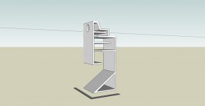
Couple of suggestions re the renders Tom.
Firstly, assuming the volume of the air-cavity to the rear of the driver isn't too great, be careful you don't make it too shallow. I've done a few shallow ones, but I've also placed the throat directly behind the driver in those cases so it reduces reflections back through the cone, which can cause smearing through the midrange & in the time-domain. If you do find it a bit shallow, there's nothing to stop you tweaking the dimensions so that upper part is narrower than the rest of the cabinet. Just a thought.
The other is: final expansion-stage. If you can angle it, that would be worth doing to smooth things out as it approaches the mouth / terminus. You seem to have ended up (a bit like I did actually) with something similar to Olson's Studio Horn folding scheme, which is no bad thing.
I like it.
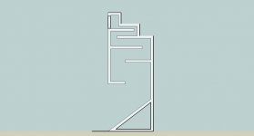
Hmm, ok, well I have a final plan but maybe I should tweak to take your suggestions in to account. Here is a copy of the actual cross section of the final horn. The depth of the cc is 2.5. I have also used shallow cc's before but stuffed them with about 1/2 pound per foot of stuffing. I didn't notice a problem but maybe there were some that I didn't notice?
In addition, I may tweak some more but if anyone is interesting in a build of my design I can email specific dimensions for those beta testers to work with.
Tom
In addition, I may tweak some more but if anyone is interesting in a build of my design I can email specific dimensions for those beta testers to work with.
Tom
Attachments
Scottmoose said:Couple of suggestions re the renders Tom.
Firstly, assuming the volume of the air-cavity to the rear of the driver isn't too great, be careful you don't make it too shallow. I've done a few shallow ones, but I've also placed the throat directly behind the driver in those cases so it reduces reflections back through the cone, which can cause smearing through the midrange & in the time-domain. If you do find it a bit shallow, there's nothing to stop you tweaking the dimensions so that upper part is narrower than the rest of the cabinet. Just a thought.
The other is: final expansion-stage. If you can angle it, that would be worth doing to smooth things out as it approaches the mouth / terminus. You seem to have ended up (a bit like I did actually) with something similar to Olson's Studio Horn folding scheme, which is no bad thing.
I like it.
I have played with the terminus smooting and it seems no matter what I do, I end up altering my flair pretty heavily by angling the last stage (if I understand you correctly I believe you thought I should angle the board at the top of the mouth). If you are refering to the bottom of the mouth, I was considering curving that ala Fostex stacking to smooth it. on the top of the mouth I could acieve the same with half inch stock. As you see in the pic, I have managed to rework the CC in hopes of standing wave cancellation. Any thoughts are appreciated.
Tom
Attachments
Nice touch with the back-chamber (not a CC remember -the room is your CC).
Yes, it was the upper panel I was refering to. It changes the flare, though as you appear to be using stepped expansion for the majority of the cabinet, that's not quite as critical as it can only approximate a given profle. What it will do is provide greater end-correction & a reduce distortion somewhat. That's not something that shows up in most software very well though -I suspect only Ron's private stuff and Earl's SPEAK would show this more clearly. Just a thought to look into anyway.
Yes, it was the upper panel I was refering to. It changes the flare, though as you appear to be using stepped expansion for the majority of the cabinet, that's not quite as critical as it can only approximate a given profle. What it will do is provide greater end-correction & a reduce distortion somewhat. That's not something that shows up in most software very well though -I suspect only Ron's private stuff and Earl's SPEAK would show this more clearly. Just a thought to look into anyway.
that's not quite as critical as it can only approximate a given profle. What it will do is provide greater end-correction & a reduce distortion somewhat.
Yep, to me its actually closer to a horn profile than the steps used in the Foxtex designs which are primarly TL sections. I do not know the dimensions but the filter chamber appears large(volume) wich will have little loading at low frequencies. In this case its more of a BVR or somewhere in between.
The major problem with small limited displacement drivers is cone control at low frequencies. The excessive movement of the cone distorts the higher frequencies as the input of a broad range of frequencies occurs at the same time. If the VC is a greater distance from the magnetic field when a higher frequency is introduced then there is a lesser mechanical effect of cone movement as there is less repulsive energy from the opposing magnetic fields.
Again this is more of a problem with smaller drivers with limited xmax and low Qts.
My solution, load the hell out of the driver and really make it work like a short stroke piston. Let the TL/horn action do the work, not the driver.
ron
Ron
I do not know the dimensions but the filter chamber appears large(volume) wich will have little loading at low frequencies.
The speaker is actually quite small. 37 high / 14 square. The back chamber is only 2.12 liters which to my calcs should be dead on the money.
Ron
My solution, load the hell out of the driver and really make it work like a short stroke piston. Let the TL/horn action do the work, not the driver.
with a 2.12 liter chamber will that be loading the hell out of it? That seems to be what the calculations call for but as I have not played with resizing back-chambers from calculated specs in the past I don't know for sure.
Scott
Yes, it was the upper panel I was refering to. It changes the flare, though as you appear to be using stepped expansion for the majority of the cabinet, that's not quite as critical as it can only approximate a given profle. What it will do is provide greater end-correction & a reduce distortion somewhat. That's not something that shows up in most software very well though -I suspect only Ron's private stuff and Earl's SPEAK would show this more clearly. Just a thought to look into anyway.
I will do my best to get this to a state that seems agreeable. I will work on it after dinner tonight. (The wife has not forgotten that it is my night to cook ).
ronc said:My solution, load the hell out of the driver and really make it work like a short stroke piston. Let the TL/horn action do the work, not the driver.
Likewise. Seems to be about the best compromise for a back-loaded horn, especially with a long and relatively slow initial expansion. The folding should help kill HF leakage without needing a whole load of damping which just messes all those delicate harmonic shadings & microdynamics up into the lower midrange.
I'm lucky -nobody will let me cook, after I asked a few years back if anyone fancied trying one of my latest roadkill recipies.
I'm not Ron, but assuming a sensible throat area, pretty much, yes. That chamber is roughly the same size as that in Ed's Horns (IIRC), the Frugel-horn & Ron's A126.
I'm not Ron, but assuming a sensible throat area, pretty much, yes. That chamber is roughly the same size as that in Ed's Horns (IIRC), the Frugel-horn & Ron's A126.
- Status
- This old topic is closed. If you want to reopen this topic, contact a moderator using the "Report Post" button.
- Home
- Loudspeakers
- Full Range
- Horn/Transmission line help