Eva said:I can assure that Hornresp is quite accurate as long as the wavelenghts considered are not too short in comparison with horn dimensions.
I hope that you mean "Hornresp is quite accurate as long as the wavelenghts considered are large in comparison with horn dimensions." because I would dispute the claim as you stated it.
RE hornreps interface
What surprised me that if there are zeroes, double clicking on S1 segment offers a curve selection dialogue; any other case it brings up a dialogue that calculates values - this is a bit inconsistent
as I said before - I can live with that")
POsted by David McBean
It should not be necessary to start a new design or null all the contour-related fields before you can change the contour. If the existing profile is Con, Exp, Hyp or Sph, and you are in edit mode, simply click the relevant segment length input box to highlight it, and then press the appropriate keyboard key to input the first letter of the profile you want to change to. If the existing profile is Lec, Obl or Tra, and you are in edit mode, simply double-click on the profile label to change back to the Con default, and then input the first letter of the profile you require (if that is not Con).
What surprised me that if there are zeroes, double clicking on S1 segment offers a curve selection dialogue; any other case it brings up a dialogue that calculates values - this is a bit inconsistent
as I said before - I can live with that
Scottmoose said:No offense intended by the interface remark David -we all appreciate the effort you put in, and I know it's deliberately done in that way.
Thanks Scott - no offence (Aussie spelling) taken
.You are perfectly right - the Hornresp interface is a bit "clunky", but I like it that way
.Kind regards,
David
Scottmoose said:That said, if modelling software like Hornresp, MathCAD et al based on the 1 dimensional wave equation get you in roughly the right neighbourhood, at least that's a start.
Hi everyone,
It is perhaps worth pointing out that Hornresp uses an isophase wavefront model for single-segment horns, rather than just a simple traditional Webster plane-wave approximation. While still not perfect, this results in more accurate predictions of throat acoustical impedance in rapidly flaring / large mouth horns (eg full-mouth tractrix, spherical and Le Cléac’h horns). The analysis is still of "one-parameter" or "1P" form.
Kind regards,
David
Re: RE hornreps interface
Hi deiksac,
As explained on page 8 of the Hornresp Help file, double-clicking on any horn segment parameter input box in edit mode will activate the Horn Segment Wizard. Only if there is a zero in the axial length input box will the Horn Flare selection form open first. This is because with a zero length value the flare is unknown (by definition), and needs to be specified before the main calculation Wizard can operate.
Entirely logical and consistent, I would have thought.
Kind regards,
David
deiksac said:What surprised me that if there are zeroes, double clicking on S1 segment offers a curve selection dialogue; any other case it brings up a dialogue that calculates values - this is a bit inconsistent.
Hi deiksac,
As explained on page 8 of the Hornresp Help file, double-clicking on any horn segment parameter input box in edit mode will activate the Horn Segment Wizard. Only if there is a zero in the axial length input box will the Horn Flare selection form open first. This is because with a zero length value the flare is unknown (by definition), and needs to be specified before the main calculation Wizard can operate.
Entirely logical and consistent, I would have thought
.Kind regards,
David
David McBean said:
It is perhaps worth pointing out that Hornresp uses an isophase wavefront model for single-segment horns, rather than just a simple traditional Webster plane-wave approximation. ... The analysis is still of "one-parameter" or "1P" form.
I'm hoping that you will explain this (isophase wavefront model )as I am not sure that I know what you mean unless you are saying that the analysis is based on the "one-parameter" forms as defined by Morse in "Vibration and Sound - 1932"- which are still based on Websters Eq. And if you don't use Websters Eq., then what do you use?
If it is the case that you are using the "1-P" approach, then I think it noteworthy to point out that Morse himself dropped the "1-P" approach in his later book "Methods of Theoretical Physics - 1953" (which post-dates "Acoustics and Vibrations" by a couple of decades) for good reason. He defines the only place (to my knowledge) that puts the true limits on Websters Equation and shows how a "1-P" solution is vitually impossible in any device of a significant size. Only a full solution of the full Wave Equation has ever been shown to be accurate for a horn/waveguide at wavelengths comparable to the waveguide itself.
gedlee said:I'm hoping that you will explain this (isophase wavefront model)
Hi Earl,
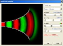
Hornresp assumes that the wavefronts travelling down the horn are curved, not plane. The actual shape of the wavefront, and hence the rate of surface area expansion, are determined by the flare profile of the horn.
The attached screenprint of the default tractrix horn in the Hornresp Wavefront Simulator tool will give you some idea of what I mean.
As mentioned before, the model is not perfect, but it works for me
.Kind regards,
David
Attachments
Re: Re: RE hornreps interface
Kinda I should get used to reading manuals for design tools and not expect to be handle everything
Cheers
Dan
David McBean said:
Hi deiksac,
As explained on page 8 of the Hornresp Help file, double-clicking on any horn segment parameter input box in edit mode will activate the Horn Segment Wizard. Only if there is a zero in the axial length input box will the Horn Flare selection form open first. This is because with a zero length value the flare is unknown (by definition), and needs to be specified before the main calculation Wizard can operate.
Entirely logical and consistent, I would have thought
Kind regards,
David
Kinda
I should get used to reading manuals for design tools and not expect to be handle everything Cheers
Dan
David McBean said:
Hornresp assumes that the wavefronts travelling down the horn are curved, not plane. The actual shape of the wavefront, and hence the rate of surface area expansion, are determined by the flare profile of the horn.
Perhaps your approach is proprietary and I understand, but as a physicist I am still interested in your math. One cannot simply assume a curvature and determining what it is is the critical point. And what about the diffraction caused by too sharp of a curvature such that the wavefront cannot remain attached to the surface? How is that handled? These aspects don't affect the loading of the horn, or the axial response to as large degree, but they are dominate in determining the directivity. Its one thing to predict loading and axial response, but its an order of magnitude more difficult (or more) to get the directivity right. To me, waveguides or horns are dominately directivity control devices, the loading is pretty much irrelavent.
Eva said:For midrange and high frequencies, loading is as relevant as directivity. With compression drivers, loading must be analyzed and optimized for low distortion and high efficiency in the pass band.
I have to disagree here since "distortion" in a compression driver is irrelavent (see my AES paper) and "efficiency" is not very important when amplifier power is readily available. Compression drivers are usually far more efficient than the LF devices anyway and have to be padded down. However, only a waveguide can provide for constant directivity, making it the only way to achieve this requirement.
Re: Re: Re: RE hornreps interface
Hi Dan,
That's what I like to hear.
Kind regards,
David
deiksac said:I should get used to reading manuals for design tools
Hi Dan,
That's what I like to hear
.Kind regards,
David
Hi Earl,
I agree. Hornresp uses finite element analysis techniques to construct the wavefront shape, taking into account the flare profile geometry of the horn.
It's not. I've never said that Hornresp is perfect . The program was originally intended to be used as more of a teaching aid than a highly accurate simulator.
User feedback would indicate that bass horn predictions are not too far off though, and I have received data from the P.audio System Company in Thailand (who also use Hornresp) showing that the program can be reasonably accurate when considering mid-range designs with compression drivers.
Once again, I have to agree. It took me more than 12 months to develop the Hornresp directivity model. Polar diagrams generated by the Directivity Pattern tool have been checked against horn directivity data published in Harry Olson's "Acoustical Engineering". The comparisons are actually not too bad, all things considered.
Kind regards,
David
gedlee said:One cannot simply assume a curvature and determining what it is is the critical point.
I agree. Hornresp uses finite element analysis techniques to construct the wavefront shape, taking into account the flare profile geometry of the horn.
gedlee said:And what about the diffraction caused by too sharp of a curvature such that the wavefront cannot remain attached to the surface? How is that handled?
It's not
. I've never said that Hornresp is perfect . The program was originally intended to be used as more of a teaching aid than a highly accurate simulator.User feedback would indicate that bass horn predictions are not too far off though, and I have received data from the P.audio System Company in Thailand (who also use Hornresp) showing that the program can be reasonably accurate when considering mid-range designs with compression drivers.
gedlee said:Its one thing to predict loading and axial response, but its an order of magnitude more difficult (or more) to get the directivity right.
Once again, I have to agree
. It took me more than 12 months to develop the Hornresp directivity model. Polar diagrams generated by the Directivity Pattern tool have been checked against horn directivity data published in Harry Olson's "Acoustical Engineering". The comparisons are actually not too bad, all things considered.Kind regards,
David
Hi Earl,
Yes, you have shown that the distortion is not immediately evident, even when comparing directly to the original signal. There is however one thing I would like to know:
Has there been any investigations on listening fatigue? That is, will a listener get fatigued more quickly when listening to a high distortion system (where, of course, the distortion is not immediately evident) than when listening to a low distortion one?
I'm not sure if compression driver distortion can be considered irrelevant without knowing this.
(OT: since compression driver distortion is predominately low order, your investigation would maybe also indicate that tube amps should not be rejected because of their higher THD ).
Best regards,
B
I have to disagree here since "distortion" in a compression driver is irrelavent (see my AES paper)
Yes, you have shown that the distortion is not immediately evident, even when comparing directly to the original signal. There is however one thing I would like to know:
Has there been any investigations on listening fatigue? That is, will a listener get fatigued more quickly when listening to a high distortion system (where, of course, the distortion is not immediately evident) than when listening to a low distortion one?
I'm not sure if compression driver distortion can be considered irrelevant without knowing this.
(OT: since compression driver distortion is predominately low order, your investigation would maybe also indicate that tube amps should not be rejected because of their higher THD
).Best regards,
B
Hi Earl,
Considering that most modern designs use the compression driver mostly above the mass rolloff frequency (typically 2-3k, ~5k for the TAD beryllium drivers), the loading property of the horn is not very relevant at these frequencies.
But when horn drivers are used below their mass rolloff, as in bass and midrange horns, where the driver works in its resistance controlled region, loading gets more important. Keeping the acoustic load smooth and mainly resistive can only improve impulse response.
Regards,
B
To me, waveguides or horns are dominately directivity control devices, the loading is pretty much irrelavent.
Considering that most modern designs use the compression driver mostly above the mass rolloff frequency (typically 2-3k, ~5k for the TAD beryllium drivers), the loading property of the horn is not very relevant at these frequencies.
But when horn drivers are used below their mass rolloff, as in bass and midrange horns, where the driver works in its resistance controlled region, loading gets more important. Keeping the acoustic load smooth and mainly resistive can only improve impulse response.
Regards,
B
Has there been any investigations on listening fatigue? That is, will a listener get fatigued more quickly when listening to a high distortion system (where, of course, the distortion is not immediately evident) than when listening to a low distortion one?
I'm not sure if compression driver distortion can be considered irrelevant without knowing this.
(OT: since compression driver distortion is predominately low order, your investigation would maybe also indicate that tube amps should not be rejected because of their higher THD
No, listener fatigue has not been studied by anyone in any context to my knowledge. I don't even know if its been shown to be a real effect, a personal thing, or completely unrelated to the sound system. I tend to believe that it has more to do with frequency response than nonlinearity. Do you have data (other than a personal opinion) to say that distortion does lead to listener fatigue? Clearly if the listener is not even aware of nonlinear distortion then the implication is that its not an issue.
Since THD as an indicator of perception is meaningless, one should not reject anything because it has high THD (but what about listener fatigue?
Kolbrek said:
But when horn drivers are used below their mass rolloff, as in bass and midrange horns, where the driver works in its resistance controlled region, loading gets more important. Keeping the acoustic load smooth and mainly resistive can only improve impulse response.
If by "loading" you mean the internal resonances of the device then I completely agree, but loading usually means to most people "cutoff" (a concept that I abhore because it doesn't really exist). It's that form of "loading" that I claim is unimportant because it is basically the same for all shapes connecting a common throat and mouth. Sure there is a low frequency roll-off associated with a compression driver on a waveguide, but this roll-off is a combination of effects, but is mostly caused by the drivers resonance frequency. This roll-off has to be considered, but the waveguide shape has very little effect on this and what effect it does have is mostly due to the mass loading, not the resistive loading.
Its the compression ratio in a driver/horn combination that has the most effect on "loading" not the shape of the horn.
Polar diagrams generated by the Directivity Pattern tool have been checked against horn directivity data published in Harry Olson's "Acoustical Engineering". The comparisons are actually not too bad, all things considered.
Unfortunately I have to report that this text is filled with erroneous data. It has been shown to be incorrect on a number of occasions. Dr. Olson seems to have made up a lot of his curves based on what he "figured" would happen. I ceased using it a long time ago.
But I would be interested in seeing if your program can model my waveguides for which I have voluminous measured data. How could I do that?
Do you have data (other than a personal opinion) to say that distortion does lead to listener fatigue?
Unfortunately not. Since I'm not connected to any research institution or company that could do such investigations, it is also hard for me to conduct a test.
I also belive that frequency response has something to do with it, also the state the person is in, if he/she is occupied with something else when listening, the average level, how much the music is compressed (dynamically), the type of distortion present and so on.
So a test for listening fatigue would need to be very carefully engineered indeed.
Since THD as an indicator of perception is meaningless, one should not reject anything because it has high THD (but what about listener fatigue?
Completely agreed, I have read your GL Metric papers
About listener fatigue, I would say we do not have enough data on the effect of long term exposition to distortion to judge how important it is.
Best Regards,
B
If by "loading" you mean the internal resonances of the device then I completely agree, but loading usually means to most people "cutoff" (a concept that I abhore because it doesn't really exist).
I'm not entirely shure I understand what you mean here. But by loading I mean using the horn (through the compression ratio transformer) as a termination to the electro-mechanical bandpass filter that the driver is. By making this termination resistive and as free of peaks (both resistive and reactive) as possible (within practical and necessary limits of course), the frequency response will be improved. Since a resistive termination free of peaks also is consistent with reducing reflections in the horn and thus reducing time domain distortions, we kill two birds with one stone
To me, loading does not mean cutoff, as cuttoff is where the load drops
It does not exist in finite horns, as there will always be a resistive component in the throat impedance below the so-called cutoff frequency, and the horn mainly adds a mass reactance here.It's that form of "loading" that I claim is unimportant because it is basically the same for all shapes connecting a common throat and mouth.
You mean the cutoff concept here, right? I would say the importance of cutoff related issues depends on how close the cutoff is to the pass band of the driver/horn combination. In bass horns (which I believe you are not much involved in designing), it gets more important. But given too small mouth, wich is common, there is virtually not difference on horn shapes.
This roll-off has to be considered, but the waveguide shape has very little effect on this and what effect it does have is mostly due to the mass loading, not the resistive loading.
True, but high resistive loading also affects diaphragm displacement, which can be important sometimes. The picture is complex here, and the relative importance of the factors depends on the frequency range of the horn/driver combination.
Its the compression ratio in a driver/horn combination that has the most effect on "loading" not the shape of the horn.
Sure, since it determines the ultimate value of the terminating impedance.
Horn design is, as you say, a though nut to crack, but one of the most fascinating things I work with. Reading, writing software, building and measuring.
I do, BTW, want to thank you for the all the interesting and useful work you have done on horns/waveguides, I believe I have read all your JAES papers on that topic
But we (I) are maybe throwing this thread far off topic - sorry for that.
Best regards,
B
- Status
- This old topic is closed. If you want to reopen this topic, contact a moderator using the "Report Post" button.
- Home
- Loudspeakers
- Multi-Way
- Horn Design - Sanity Check