gedlee said:You claim this to be a far field response, with no electronic manipulation of the frequency response? If so, then I don't believe this plot either.
Hello,
same driver on a Fc=204 horn (previous one was on a fc=160Hz horn):
http://www.azurahorn.com/Yamaha_on_204.pdf
Best regards from Paris,
Jean-Michel Le Cléac'h
Hi Earl
You mentioned, “unless EQ'd with a complex filter set (as in Tom Danley's plots).”
Understand, this is the measured response w/5% smoothing (1 / 20 oct) at 10 meters half space when driven with a 28 Volt Rms, Swept sine (TDS), there is no eq involved, no DSP, nothing, it really is this flat right off the bat.
Now I am confused too, normally one finds the level of 112 dB at one meter from an omni point source in half space as being the level one measures with one acoustic Watt.
For example; http://www.trueaudio.com/post_002.htm
This figure correlates with the T&S parameter reference efficiency too where 1% efficiency would produce about 92dB 1W, 1M.
By Watts of course in this case meaning “speaker Watts” (roughly Volt Amps at best) based on a Voltage into the nominal load R. In general, this tradition overstates the power level compared to real Watts which makes the spec sheet numbers better.
In the case if the four TH115’s, the impedance of the series parallel load presents is 8 Ohm or above “in band” so that a 2.8V @ 1M or 28V drive @ 10 meters presents less than 1 or 100 speaker Watts actual total drive. Accounting for distance, this is a sensitivity of 108 to 110 dB 1W (total nominal power) at one meter.
In this case, even 1Vrms into the system 8 Ohm load produces 99 to 101 dB @ 1 meter.
Given the traditional rough estimation of efficiency (Via SPL at one meter at one Watt nominal), this setup would appear to be around 30-40% efficient.
Keep in mind that is +12 to +14dB more sensitive per nominal Watt than one driver is, when used as a direct radiator.
If one takes the actual impedance “in band” into account (which is increased due to the acoustic load compared to out of band) , then it is somewhat higher depending on frequency.
I would draw distinction between this case and a compression driver, these are normally used well past the efficient range of operation, for a one-inch exit driver, that might be 2-4 KHz or so at the high end, while used 2 octaves higher. Thank heaven for DI up high.
I have been real busy, are you back in the states or overseas still?
Best,
Tom
David McBean said:
Thanks for confirming that you have an Advanced Micro Devices Athlon processor. Unfortunately, this means that you are out of luck as far as running Hornresp on your existing computer is concerned.
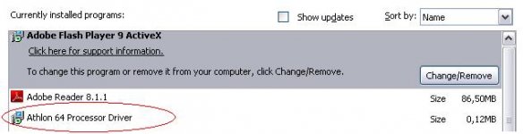
I can run Hornresp on AMD Athlon XP, Athlon 64 and Athlon 64 X2. I know that the x2 have some rare problems with certain applications. Installing the AMD processor driver has cured the few problems I've had with the dual core processor (x2).
It's a mystery why MS does not include this driver through MS update, when driver being WHQL certified and all.
I don't know in this specific case but this could be something that might help get Hornresp up and running.
gedlee, do you have this driver installed, pictured below?
Attachments
gedlee, do you have this driver installed, pictured below?
What does Remote Desktop have to do with anything?
Tom Danley said:Hi Earl
Understand, this is the measured response w/5% smoothing (1 / 20 oct) at 10 meters half space when driven with a 28 Volt Rms, Swept sine (TDS), there is no eq involved, no DSP, nothing, it really is this flat right off the bat.
I have been real busy, are you back in the states or overseas still?
I was there all summer (4 months), now there is some concern about finances so I'm in the states untill this is settled out.
I am not used to seeing curves this flat, even from raw drivers (and I know the TBX15-100 well and its NOT that flat). I'm not going to quible, but this does not look normal considering cabinet diffraction, etc. Perhaps your ground plane makes things look better - I don't use that method and I don't really like it because of all the assumptions. Maybe 10 meters is an issue since this is not very common either. If you are optimizing for axial flatness then I suppose this is possible, so until I saw a complete polar map, I really couldn't comment further.
gedlee said:I have five computers and two laptops - not one of them uses Intel. This explaination does not make sense to me either since SPEAK is written in VB (version 3 through 6) and it never had a problem that was CPU dependent. And its not like AMD is some abscure hardware - all HP computers use AMD. I now only use HP computers because of the performance and reliability that I have seen over the years.
Hi Earl,
It would seem that sometimes, Hornresp just doesn't like AMD Athlon processors
") . There is a note to this effect in the "Known Problems" section of the Readme.txt file (supplied as part of the progam download package). You can see from the fault list that very few operating problems have been reported, even though Hornresp has a relatively large user base.
. There is a note to this effect in the "Known Problems" section of the Readme.txt file (supplied as part of the progam download package). You can see from the fault list that very few operating problems have been reported, even though Hornresp has a relatively large user base.I have only one computer - a HP Pavilion desktop - it came with an Intel processor.
Kind regards,
David
4fun said:I can run Hornresp on AMD Athlon XP, Athlon 64 and Athlon 64 X2. I know that the x2 have some rare problems with certain applications. Installing the AMD processor driver has cured the few problems I've had with the dual core processor (x2).
Thanks 4fun. I was not aware that there might be a relatively simple solution to the Athlon problem.
Kind regards,
David
gedlee said:You claim this to be a far field response, with no electronic manipulation of the frequency response? If so, then I don't believe this plot either.
Hello,
Those measurements were done by Martin Seddon on Azura horns calculated by my method.
Martin Seddon used only a +6dB/octave "Constant Directivity-like" equalization above 3500Hz. There is NO equalization below 3500Hz.
Best regards from Paris,
Jean-Michel Le Cléac'h
Jmmlc said:
Hello,
Those measurements were done by Martin Seddon on Azura horns calculated by my method.
Martin Seddon used only a +6dB/octave "Constant Directivity-like" equalization above 3500Hz. There is NO equalization below 3500Hz.
Best regards from Paris,
Jean-Michel Le Cléac'h
I see from your previous plot that these are taken at "the horn mouth" hence they are not the actual sound radiation and ignore a huge number of very important effects in the device. With 110 dB range on the plot and this mouth measurement limitation its impossible to say if this is any good or not.
I always try and do measurements that show up problem, not hide them (thats marketings job). Its no wonder measurements get such a bad name when this kind of thing is done.
If you want to show a meaningful measurement do a true free field (not ground plane), far field (at 3 meters), full polar response (7.5° resolution minimum) and then plot it with a maximum vertical scale of 40 dB. Your devices won't look so good done that way.
horns nearing completion
Okey guys, I have progressed with theconstruction to the point that both horns can be tested see gallery at http://deiksac.multiply.com/photos/album/17/RootsnFuture_Horn
The monsters are to be tested on saturday, I am pretty curious - according to the TS params, each horn should be capable of delivering 134 dB peak (1m) so I am wondering whether they will be able to keep up with the rest of the system (which comprises of many hornloaded 18" speakers - count varies from 4-12, the constructions is a folded horn from Turbosound with PD 186 inside)
Since the driver chamber is pretty small and the driver should be capable of hanfling extreme amounts of power (theytold me 1200W peak) I am a bit worried about the temperature. The driver has a vented voice coil - what if I made an opening just behind it so that the air circulates at least a bit? This would mean a vented rear chamber - thru the spider and speaker magnetic gap.
How would that influence horn behaviour? Since the speakers are pretty expensive I would be happy not baking them
Okey guys, I have progressed with theconstruction to the point that both horns can be tested
see gallery at http://deiksac.multiply.com/photos/album/17/RootsnFuture_HornThe monsters are to be tested on saturday, I am pretty curious - according to the TS params, each horn should be capable of delivering 134 dB peak (1m) so I am wondering whether they will be able to keep up with the rest of the system (which comprises of many hornloaded 18" speakers - count varies from 4-12, the constructions is a folded horn from Turbosound with PD 186 inside)
Since the driver chamber is pretty small and the driver should be capable of hanfling extreme amounts of power (theytold me 1200W peak) I am a bit worried about the temperature. The driver has a vented voice coil - what if I made an opening just behind it so that the air circulates at least a bit? This would mean a vented rear chamber - thru the spider and speaker magnetic gap.
How would that influence horn behaviour? Since the speakers are pretty expensive I would be happy not baking them
Trust that the power specs are pretty liberal (hence Peak power handling!)
The heat must be able to get out of the rear chamber somehow and wood is a good insulator. small vent holes - not too many - should help, but they could also change things considerably. Very small holes have high resistance which will help, Don't use one big hole, use many small ones, with holes on opposit sides for flow through ventillation.
The heat must be able to get out of the rear chamber somehow and wood is a good insulator. small vent holes - not too many - should help, but they could also change things considerably. Very small holes have high resistance which will help, Don't use one big hole, use many small ones, with holes on opposit sides for flow through ventillation.
i have thought to make one hole say 1 inch in diameter to match the dia of the voice coil ventilation gap so that air might move freely there ....
what i would love to know is the speakers xmax, hornresp predicts some 3 mm excursion somewhere around 100 hz, which should be okay, since I would love to cross it first or second order in the area of 140 Hz - in this respect I should be okay - but on the other hand - limited excursion does not help heat transfer much .... anyway worst case I can make a completely new spekaer cover, maybe could be an aluminium one
keep your fingers crossed for the voice coils
I wouldn't worry too much about excursion since you will likely burn up the device before you have audible excursion problems. But a 1" hole would be a disaster. I was thinking more like 10 1/16" holes on the top side and another 10 on the bottom side so that the internal thermal differential (heat rises) will drive air through these holes. What you want is a static flow through the holes so that the dynamic sound from the driver has to work against the static friction from the thermal differential. Done properly this will disipate a lot of heat through convection while not degrading performance too much.
this sounds smart; the thing is that the speaker will get carpeted, so holes this small will get probably lost in the carpet hairs ...
oops compromises
the speaker in the chamber touches the rear door, so what about this idea: a circle of small holes just behind the voice coil ventilation gap (where the carpet would not be applied later)? anothe disaster?
oops compromises
the speaker in the chamber touches the rear door, so what about this idea: a circle of small holes just behind the voice coil ventilation gap (where the carpet would not be applied later)? anothe disaster?
The heatsink is not a bad idea, anyway testing turned out very wel
I drilled few holes just behind the voice coil and sealed the room and also drilled four 2mm (1/12") holes on the top and bottom side as per your suggestion
Whern we turned the speakers initially up, weird sounds and resonations appeared but it turned out that the volume is too high the pair of these can easily keep up with 8 bass horns (althoug I would say their design is suboptimal)
check the pics at http://deiksac.multiply.com/photos/album/17
I would say a nice face of the syoundsystem
during the evening as the surrounds lost a bit of their stiffness the sound got butter, I would say pretty effortless
we still have to find some optimal crossover setting; I suggested shallow slope between bass and midbass at say 135 Hz and this turned pretty well; the midbass high integration was at about 500 Hz with rather steep slopes, I set some 1ms delay for the midtop part and the whole midbass/mid/top part sounded very effortless
thanks for good suggestions Earl
I drilled few holes just behind the voice coil and sealed the room and also drilled four 2mm (1/12") holes on the top and bottom side as per your suggestion
Whern we turned the speakers initially up, weird sounds and resonations appeared but it turned out that the volume is too high
the pair of these can easily keep up with 8 bass horns (althoug I would say their design is suboptimal)check the pics at http://deiksac.multiply.com/photos/album/17
I would say a nice face of the syoundsystem
during the evening as the surrounds lost a bit of their stiffness the sound got butter, I would say pretty effortless
we still have to find some optimal crossover setting; I suggested shallow slope between bass and midbass at say 135 Hz and this turned pretty well; the midbass high integration was at about 500 Hz with rather steep slopes, I set some 1ms delay for the midtop part and the whole midbass/mid/top part sounded very effortless
thanks for good suggestions Earl
- Status
- This old topic is closed. If you want to reopen this topic, contact a moderator using the "Report Post" button.
- Home
- Loudspeakers
- Multi-Way
- Horn Design - Sanity Check