Can you tell me why using 24V 15A SMPS is not good? I put inductor in series with the output and I put 40mF on each rail for each side. So I have 160mF reservoir cap total after the inductor. I don't think this will be in any way inferior to any toroidal supply.
You guys keep talking about ripple and voltage droop. I will not have droop and ripple. I would like to hear a real reason why SMPS is inferior.
The switching power supply is a strong generator of high frequency noises.
The switching power supply is a strong generator of high frequency noises.
That's the reason I have the few uH high current inductor right at the output. It's really not that bad, we used to use all analog regulated supplies in our mass spectrometers, but I changed to all SMPS and be careful on the pcb layout with ground planes. We are working with nV signals, we never have problems with noise.
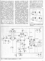
I don't understand a word on the article with the schematic!! Is that the original Hiraga schematic?
Where did you see 120 Hz sinus after rectifier diodes?
Under heavy load, you always see the ripple on an unregulated supply.
Last edited:
That's the reason I have the few uH high current inductor right at the output. It's really not that bad, we used to use all analog regulated supplies in our mass spectrometers, but I changed to all SMPS and be careful on the pcb layout with ground planes. We are working with nV signals, we never have problems with noise.
I don't understand a word on the article with the schematic!! Is that the original Hiraga schematic?
Under heavy load, you always see the ripple on an unregulated supply.
On en parle n°34 : modifs ampli Hiraga 20W, tweeter technics 5HH10 ...
I can't read the language!!!
Attachments
Thanks, now this is universal language.
Thanks
a little mistake, last caps not connected with ground.
Cause low speed for this amp, not have time to give the necessary current to the load. I have Hiraga 20W (from L'Audiophile '34 jan. 1985). With 0,404F summary filter and 2*160W transformers on high frequencies it has some "metallic overtones" into Martin Logan Electromotion, but with 1,26F filter and 2*300W it's alright.
I've think, that better to do all as an scheme and then "start having fun".
p.s.: I don't like inductors in analog power supply even for digital.
Hello ,
Later the people where you could buy the parts for the Hiraga amp in Paris did start using inductors ( 200mH 2,5 A) in some of their designs like the nemesis and a 50 watt Kaneda based amp. At that time i was in the proces of building Le classe A ( with the 330.000mF caps) and i did ask them if i could use that choke in Le classe A. Sure, good idea but they did give it a lot of attention because probably they still had a stock of chassis where the choke would be difficult to mount) I had some friends with the right machinery so it was easy for me.
I would suggest people to buy a set of Lundahl chokes ( ll1694) and try them in their 20 or 30 watt hiraga. There will be some extra voltage drop but that will be ok.
Greetings, Eduard
Hi.
Maybe, maybe.
About CRC vs. CLC - it's only my opinion.
p.s.: I don't like stabilizators in analog power supply.
Hello ,
Later the people where you could buy the parts for the Hiraga amp in Paris did start using inductors ( 200mH 2,5 A) in some of their designs like the nemesis and a 50 watt Kaneda based amp. At that time i was in the proces of building Le classe A ( with the 330.000mF caps) and i did ask them if i could use that choke in Le classe A. Sure, good idea but they did give it a lot of attention because probably they still had a stock of chassis where the choke would be difficult to mount) I had some friends with the right machinery so it was easy for me.
I would suggest people to buy a set of Lundahl chokes ( ll1694) and try them in their 20 or 30 watt hiraga. There will be some extra voltage drop but that will be ok.
Greetings, Eduard
Did you hear Jean Hiraga's 50W amp?
Attachments
Hello,
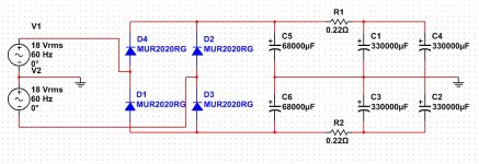
Crc versus clc. At that time the french did do some measurements and some listening test and told the diy community that clc was way better.
Of course yoiu should take care that serie resiostance of the choke is not to high. The choke used by the french was 0,8 ohm. The resistor in the hiraga amp was 0,22 ohm or a bit higher if your power supply voltage was to close to the voltage rating of the caps. But usually it were the caps before the resistor that did break down. Better use 40 volts caps for these ones if you have a big transformer whose voltage will not drop when the amp is ringing.
The ll1694 are not expensive, only need two,
Greetings, Eduard
Not to mention it's a Class A, current variation is very small.
Average mains current may be fixed but the actual signal current runs from ground back through the power supply to the supply rails. And 40kHz is barely Nyquist so your SMPS is not going to be "in control" of the rails above 8kHz (allowing the usual engineering rule of thumb of 5x oversampling) never mind keeping power supply noise 60db down.
Mr. Hiraga specified a massive power supply to achieve particular (audible) characteristics.
He is not alone: e.g. Peter Stein (of ME Amplifiers) puts "excessive" amounts of capacitance on the rails - and also for audible results.
Trying to build an amplifier design while changing the power supply is a supreme folly: the power supply is half of the amplifier.
You can't add another PS to the Hiraga signal section and still call it a Hiraga.
I agree with that... Built several Hiraga and one is half in way
Now you are talking about droop, transformer droop also particular it's not even regulated.
I never said use the SMPS alone. I am going to have filter caps. At least 20,000uF for each rail.
I never understand why supply is half the design. You want stiff voltage rail, that's about all you can ask for. Charging at 40KHz sure beats charging at 120Hz. I bought two 24V SMPS that are 15A for less than $50. I don't think you can touch a toroidal transformer + rectifier + lot more cap with that price .
Did people actually try SMPS or just the idea it has more noise? In the older days, we also believed in using linear supplies for the mass spectrometers because we need to detect nV and pA range. I changed to all SMPS and saving racks of space and cost a lot less. Nobody complained. We automatically use SMPS on all the new instruments now.
Last edited:
ClassA output current is the CHANGE in supply rail current, except for the very few ClassA topologies that are nearly constant current....................... Not to mention it's a Class A, current variation is very small......................
PP ClassA works much the same:
ClassA output current is the DIFFERENCE in supply rail currents.
In both the classes, SE and the PP version, if the supply rail current does not change, then the output current must remain as zero !
Sorry I did not read all the posts. Did anyone use switching supply for this. You can get all sort of low voltage supplies really cheap. You don't need a whole lot of big caps as it's already regulated. You need choke and high frequency smaller caps only. (well one big cap for each rail if you feel more comfortable.)
Just checking.
It regulates. Quite well. In fact.
But it has high freq oscillation (like a sawtooth) that you have to filter out. Chokes should be put in the feeding lines and still then set of caps are needed to filter it out.
The amplifier has PSRR but this 'noise' tends to end up on the ground plane too . .
It regulates. Quite well. In fact.
But it has high freq oscillation (like a sawtooth) that you have to filter out. Chokes should be put in the feeding lines and still then set of caps are needed to filter it out.
The amplifier has PSRR but this 'noise' tends to end up on the ground plane too . .
Thank you. That's what I try to convey. I was once guilty of refusing to use SMPS just because I saw the high frequency glitches on the line that you need to be careful using filter. A small toroid to wrap a few turns on the cable from the output of the supplies, filter caps, good layout on pcb so it's less susceptible to EMI radiation, then it's all good.
I worked in designing mass spectrometers/semi conductor test equipments, we measured very low current and voltages. We used to have racks of linear regulated supplies until I decided to switch all to SMPS. They worked great, we starting to have small SMPS modules on pcb and all. It saved a lot of space, power.
Well, of cause, if people are using an imperfect supply to create sag to give certain effect on the sound like guitar amps, then it's a different story. But if stiff supply rail is what you are after, I cannot imagine you can do better with an unregulated transformer/rectifier/big filter caps. In fact, I don't think you can even tough the regulation of an SMPS.
Problem with using SMPS for normal Class AB is because you need 48V and higher, SMPS cost a lot of money for higher voltage, that make it not worth your while. Also, the normal design of the 2EF/LTP topology has much better PSRR than the Hiraga, sag is no even an issue.
But for Hiraga that use 20V rail, it's perfect to use 24V SMPS that is cheap like dirt. You just adjust down to 20V!!! You want sag, put a 0.22ohm and filter caps like the schematic of the supply used!!!
I cannot imagine the SMPS will droop more than any of the transformer. Still worry, get a 20A+ SMPS, you are not going to droop!!!
Hello,
Crc versus clc. At that time the french did do some measurements and some listening test and told the diy community that clc was way better.
Of course yoiu should take care that serie resiostance of the choke is not to high. The choke used by the french was 0,8 ohm. The resistor in the hiraga amp was 0,22 ohm or a bit higher if your power supply voltage was to close to the voltage rating of the caps. But usually it were the caps before the resistor that did break down. Better use 40 volts caps for these ones if you have a big transformer whose voltage will not drop when the amp is ringing.
The ll1694 are not expensive, only need two,
Greetings, Eduard
Ok, maybe in future I'll use it.
- Status
- This old topic is closed. If you want to reopen this topic, contact a moderator using the "Report Post" button.
- Home
- Amplifiers
- Solid State
- Hiraga 20W class A