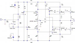
LTSpice of this amp, ahem, is very interesting.
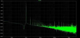
Total Harmonic Distortion 1KHz +20dBU output into 8R: 0.232734%
99.9% of this distortion is H2+H3+H4 with H2 at -53dB and H5 at -83dB for +20dBU output
0.254% THD at 20KHz, +20dB into 8R. Quiescent current is 1.39A
Phase shift at 20Khz//+20dB output into 8R resistive is 3.44 degrees
180 degree phase shift (with LP in place) is 4MHz
Gain is 18.3, that is, 25.3dB for 770mVp input and 14.14Vp output at 1KHz (+20dBU)
1dB point at 240KHz NO LOSS at DC signal
FEATURES: Poor, asymmetrical clip at 21V/27.5W into 8R.
Very high distortion artefacts, arrayed in a monotonic, almost linear reduction
Set offset cold extremely tetchy; 1R change on 500R generates 5mV offset
This should set some discussion. I have attached the LTSpice file.
Hugh
PS Ignore the Copyright issue; this is a redraw of another, original circuit.
Attachments
Last edited:
No, I am really busy trying to send my boards out tonight. I'll try to find time to do it this weekend.
But I am very intrigued with this design. It makes a lot of sense when he compare with the tube amps. Normal SS OPS are straight voltage amp with very low impedance. Efforts are made to make the output impedance as low as possible. So if the load impedance change with frequence, the power transfer to the load change with frequency also.
This design is kind of a control current source. It's the current that drive the load, so when the impedance of the load change, the voltage change along with it. So the characteristics are totally different from the conventional amp.
Granted it has GNFB, but the loop gain is low and you really don't get the full effect of the normal closed loop feedback benefit as much.
What's version you want to make?
")
Last edited:
Hugh, I`ve done the simulation you`ve attached but with the 4 ohms load, the output power doubles like in all ss amps, there is no output transformer effect as described in the original article. The harmonic structure ( never mind the high distortion) is btw as you described "arrayed in a monotonic, almost linear reduction" that you don`t get with the classic output stages. Very interesting.LTSpice of this amp, ahem, is very interesting.
Total Harmonic Distortion 1KHz +20dBU output into 8R: 0.232734%
99.9% of this distortion is H2+H3+H4 with H2 at -53dB and H5 at -83dB for +20dBU output
0.254% THD at 20KHz, +20dB into 8R. Quiescent current is 1.39A
Phase shift at 20Khz//+20dB output into 8R resistive is 3.44 degrees
180 degree phase shift (with LP in place) is 4MHz
Gain is 18.3, that is, 25.3dB for 770mVp input and 14.14Vp output at 1KHz (+20dBU)
1dB point at 240KHz NO LOSS at DC signal
FEATURES: Poor, asymmetrical clip at 21V/27.5W into 8R.
Very high distortion artefacts, arrayed in a monotonic, almost linear reduction
Set offset cold extremely tetchy; 1R change on 500R generates 5mV offset
This should set some discussion. I have attached the LTSpice file.
Hugh
PS Ignore the Copyright issue; this is a redraw of another, original circuit.
BB,
Yes, the results are quite unique. I have spent some years trying to correlate the LTSpice results with listening impressions, and I conclude that Hiraga's comment in the seventies that a monotonic distortion profile drives high levels of THD, most unconventional and universally despised, has merit. Conversely, the obsession to reduce THD below 0.0003% might just be deluded.
When you see the profile, and read the lines in some of the very well regarded writers, and then the analysis of JLH and many of Pass' circuits, you begin to see a pattern.
I suspect you have it in your sights.........
Ciao,
Hugh
Where do you get the "missing models"?LTSpice of this amp, ............. I have attached the LTSpice file.
...........
The drivers and outputs are missing.
Do the other models come straight from the LTspice library?
Where do you get the "missing models"?
The drivers and outputs are missing.
Do the other models come straight from the LTspice library?
Hi AndrewT,
Drivers can be found here.
Outputs:
.MODEL 2SA1943 PNP ( IS=1.30E-10 BF=91.42 VAF=100 IKF=4.480 ISE=1.02E-10 NE=2.0 VAR=100 ISC=5.0900E-9 NC=1.5 BR=0.882 IKR=2.9015 RE=0.0011 RC=0.0553 RB=140.05 RBM=0.0041 IRB=8.5e-9 CJE=2.00E-10 FC=0.5 CJC=9.45E-10 VJC=0.48 MJC=0.28 TF=9.250E-10 XTF=10 VTF=10 ITF=1 TR=1.00E-8 EG=0.76 XTB=2.68 mfg=Toshiba)
.MODEL 2SC5200 NPN ( IS=3.0463E-11 BF=96.20 VAF=100 IKF=15.04256 ISE=5.6190E-11 NE=2.0 BR=4.849 IKR=1.05012 VAR=100 ISC=7.18E-8 NC=1.5 RE=0.0025 RB=20.18 RBM=0.0014 IRB=1.0E-7 RC=0.01137 CJE=4.5000E-10 CJC=8.4915E-10 VJC=0.68977 MJC=0.54081 TF=6.8583E-10 XTF=9.5721 VTF=10.425 ITF=6.8697E-2 TR=1.000E-8 XTB=1.45 EG=0.82 FC=0.5 mfg=Toshiba)
Cheers,
Jacques
The one thing you have to do is not using resistor as load. If you use resistor load, together with the GNFB, it's going to be similar to the conventional SS amp.
I am starting to build my own LTSpice also. I think you need to using a circuit to simulate the speaker impedance using inductor, capacitor and resistor.
Another thing is you have to keep the loop gain low also. If you increase the loop gain, the GNFB will make the output impedance very low and defeat the quasi current output nature of the circuit.
Last edited:
BB,
Yes, the results are quite unique. I have spent some years trying to correlate the LTSpice results with listening impressions, and I conclude that Hiraga's comment in the seventies that a monotonic distortion profile drives high levels of THD, most unconventional and universally despised, has merit. Conversely, the obsession to reduce THD below 0.0003% might just be deluded.
When you see the profile, and read the lines in some of the very well regarded writers, and then the analysis of JLH and many of Pass' circuits, you begin to see a pattern.
I suspect you have it in your sights.........
Ciao,
Hugh
Do you mean monotonic distortion is H2 higher than H3, H3 higher than H4, H4 higher than H5, etc?
This is FFT from my amplifier. Is the distortion monotonic?
Attachments
Yes, Bimo, betul benar, you have it........
Your figures are pretty low, I get this fft at 20K, high, but much lower at 14.14Vp into 8R at 1KHz (+20dBA).
yth
Alan,
If you add 100nF you see little change in harmonics or even phase shift. Add 2uF, simulating an ELS63, you do see a distortion increase of 20dB for the first ten harmonics at 20KHz fundamental. At 1KHz the change is minimal, however. I agree an IHF load should be used in the simulations, however, for an amp with low global feedback stability is less affected. At very low THD amps with very heavy global feedback the situation is very difficult.
Cheers,
Hugh
Attachments
Last edited:
About the offset,
I have build a Hiraga about 20 years ago with all the long discontinued original parts and it's been stable al along. Once in a while I measure the offset voltage and it never was higher then 8mV !! That's very good i.m.o.
Offset is all over the place when you touch one of the two driver transistors so in the beginning I was afraid this thing would be unstable but just don't touch it and all is fine.
I have build a rather underpowered version with only 18V power supply and 0.8A bias current but it does sound the same as the slightly higher biased one a friend build at the same time (21V with 1.1A bias)
This thing runs hot but it's been running for over 20 years and it's a keeper. In my system it sounds better then UCD700, Tripath, NAKSA70, gainclone, 300B SET amp and some other that came and went. It just plays music in a very engaging way with tons of atmosphere and detail. It's also dead quiet as a bonus. I'm trying to replace it for years because of the heat (in summer over 65 degrees heatsinks) and electricity use but I keep coming back on it.
I am new with LTSpice. It seems like you are running larger time step or fewer cycles to speed up the simulation. From my experience, it will give lower THD. You distortion seems too low of 15dB-(-120dB)= -135dB. I run small time step and get like 50 cycles, usually takes me over an hour to run one simulation, BUT the graph is a lot cleaner with very narrow peaks. That is more accurate.Do you mean monotonic distortion is H2 higher than H3, H3 higher than H4, H4 higher than H5, etc?
This is FFT from my amplifier. Is the distortion monotonic?
I am still not familiar enough with this design. But according to the author, it's not the distortion that matter, it's how the distortion interact with the harmonics of the instrument ( can be voice also). He talked about the timber?? of the sound etc. That's what intrigues me, that he uses quasi current output that interact with the complex load of the speaker instead of brute force driving the speaker with very low impedance.If you add 100nF you see little change in harmonics or even phase shift. Add 2uF, simulating an ELS63, you do see a distortion increase of 20dB for the first ten harmonics at 20KHz fundamental. At 1KHz the change is minimal, however. I agree an IHF load should be used in the simulations, however, for an amp with low global feedback stability is less affected. At very low THD amps with very heavy global feedback the situation is very difficult.
I am new with LTSpice. It seems like you are running larger time step or fewer cycles to speed up the simulation. From my experience, it will give lower THD. You distortion seems too low of 15dB-(-120dB)= -135dB. I run small time step and get like 50 cycles, usually takes me over an hour to run one simulation, BUT the graph is a lot cleaner with very narrow peaks. That is more accurate.
I use more cycle and THD don't change to much
It is have high open loop gain. It will give low THD and I was built it, sound better than 4 commercial amplifier (and more expensive) according to my friends who compared it. To see more clear on FFT at 1kHz, I was change input and feedback capacitor to 1F
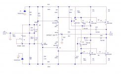
This is my rough try on the circuit. This is more a starter for conversation than a design. I have not really get into the value of the resistors or really give it a lot of thinking in the details. But two things I like to improve are the power handling as I use two pairs of power transistor. Also, the bias and offset is not good in the original circuit. I am trying to separate them into two distinct adjustments as shown.
I was first temped to add CCS to raise the open loop gain, but I think that will make it into another SS amp. To me, it's more important to preserve the low open loop gain and let the quasi current output stage shine instead of using the high loop gain to swamp out the effect.
I definitely would have close thermal coupling between Q5 & Q11 and Q7 & Q12 to minimize bias and offset drift.
Attachments
Last edited:
Member
Joined 2009
Paid Member
About the offset,
I have build a Hiraga about 20 years ago ..... I'm trying to replace it for years because of the heat .... but I keep coming back on it.
You are a lucky guy - most of us are stuck in a never ending loop of finding new things - the addiction runs strong
I am working to finish the 'other' famous Class A, the JLH69 and will see if it has the same benefit
You are a lucky guy - most of us are stuck in a never ending loop of finding new things - the addiction runs strong
I am working to finish the 'other' famous Class A, the JLH69 and will see if it has the same benefit
I'm also stuck in the upgraditis once in a while but the Hiraga stood the test of time with proud and I think it is still worth it today. It's the reason why I still have it. Lot of amps came and went in the meantime. Offcoarse it has it shortcomings like any amplifier in excistense has it's own, but is does a lot of thing so damn right you can forgive it. It's a highly enjoyable amp, not for very low sensitivity and/or difficult loudspeaker loads though. Treat it like a low powered tube amp with matching loudspeaker and you will be happy. I have not heard the versions with the newer transistors, mine is build with all the originial parts wich I bought in the good old times when I had an fantastic friendly guy with an electronics shop in town wich didn't mind I spent two days matching all the needed transistors out of hundreds. They are matched so close it's scary but I can only guess if this really paid of because I haven't build one with none matched transistors so I cannot give any conclusion on that, I only did it because mister Hiraga himself remoended to do so. Still, if I can find an amp wich runs cool with a lot less energy and sounds better I'm happy to replace it
I really don't see different transistors are that important. You need to find one with Beta that is more constant with current and does not droop at high current, High enough Vcb, lower capacitance and at least 40 to 50MHz fT. I really think anything more than that is psychosomatic.
MJL1302 and MJL3281 comes in mind as about the best you can have. It's all about the design!!! I am interested in Hiraga because of the pseudo current output stage and lower GNFB to interact with the varying impedance of the speaker load. I really think the transistor is really secondary. There is a line between science/logic and superstition/psychosomatic. I yet to have anyone explain to me why transistor A is better than B if the fT, beta droop, Vcb and capacitance are comparable. All I got is "it's proven" "everyone uses it". This is psychosomatic.
MJL1302 and MJL3281 comes in mind as about the best you can have. It's all about the design!!! I am interested in Hiraga because of the pseudo current output stage and lower GNFB to interact with the varying impedance of the speaker load. I really think the transistor is really secondary. There is a line between science/logic and superstition/psychosomatic. I yet to have anyone explain to me why transistor A is better than B if the fT, beta droop, Vcb and capacitance are comparable. All I got is "it's proven" "everyone uses it". This is psychosomatic.
Last edited:
I don't have any proof if different transistors make a difference because i didn't try. Lots of people are swapping tubes in their tube amps wich in theory also shouldn't make any difference.
All I know is that the Hiraga 20W version and the Kaneda pre-amp where not designed by Jean Hiraga himself and he never claimed he did, they where excisting designs from the late 70's. Mr.Hiraga spent a lot of time actual listening to different transistor combinations like tube rolling, bias points and power supply. In other words, he tweaked the designs and wrote a lot about the sound of different transistors, specially in the Kaneda pre-amp. I have read all the stories years ago and he is such a passionate writer it's almost hard not to believe the story (tricky, I know). So according to the story I have chased and matched the exact transistor set. That alone cost me so much time so it has to make a difference !!! No serious, I don't have any proof, sorry
All I know is that the Hiraga 20W version and the Kaneda pre-amp where not designed by Jean Hiraga himself and he never claimed he did, they where excisting designs from the late 70's. Mr.Hiraga spent a lot of time actual listening to different transistor combinations like tube rolling, bias points and power supply. In other words, he tweaked the designs and wrote a lot about the sound of different transistors, specially in the Kaneda pre-amp. I have read all the stories years ago and he is such a passionate writer it's almost hard not to believe the story (tricky, I know). So according to the story I have chased and matched the exact transistor set. That alone cost me so much time so it has to make a difference !!! No serious, I don't have any proof, sorry
- Status
- This old topic is closed. If you want to reopen this topic, contact a moderator using the "Report Post" button.
- Home
- Amplifiers
- Solid State
- Hiraga 20W class A