I think it's better to get the existing transistor and tweak the circuit to get the sound.
I design tube guitar amp, I make it a point to use the cheapest tube possible and work on the circuit to get the sound. Guitar amp should be a whole lot more sensitive to distortion as slight change in resistor value or cap value can totally change the sound. For audiophile, most of it is to lower distortion.
Too many snake oil going around. Guitar amp want distortion, I make it a point to use all metal film resistor, ceramic caps even for tone stack, Cheap chinese tube on ebay, cheap Classic Tone output transformer and cheap Weber PT. I designed and built two amps and they sounded beautiful to me.
On top, tube is really a mechanical device. I don't think transistor behave like tubes.
I still think there is a lot of psychosomatic in this when getting down to the very fine detail. Not to mention one amp sounds good to one person might sound bad to another person.
I don't have any proof if different transistors make a difference because i didn't try. Lots of people are swapping tubes in their tube amps wich in theory also shouldn't make any difference.
All I know is that the Hiraga 20W version and the Kaneda pre-amp where not designed by Jean Hiraga himself and he never claimed he did, they where excisting designs from the late 70's. Mr.Hiraga spent a lot of time actual listening to different transistor combinations like tube rolling, bias points and power supply. In other words, he tweaked the designs and wrote a lot about the sound of different transistors, specially in the Kaneda pre-amp. I have read all the stories years ago and he is such a passionate writer it's almost hard not to believe the story (tricky, I know). So according to the story I have chased and matched the exact transistor set. That alone cost me so much time so it has to make a difference !!! No serious, I don't have any proof, sorry
All I know is that the Hiraga 20W version and the Kaneda pre-amp where not designed by Jean Hiraga himself and he never claimed he did, they where excisting designs from the late 70's. Mr.Hiraga spent a lot of time actual listening to different transistor combinations like tube rolling, bias points and power supply. In other words, he tweaked the designs and wrote a lot about the sound of different transistors, specially in the Kaneda pre-amp. I have read all the stories years ago and he is such a passionate writer it's almost hard not to believe the story (tricky, I know). So according to the story I have chased and matched the exact transistor set. That alone cost me so much time so it has to make a difference !!! No serious, I don't have any proof, sorry
Member
Joined 2009
Paid Member
I do think that transistor type is a factor to be considered. I believe it depends on the amplifier topology and the differences in behaviour between the transistors. In low feedback amplifiers there's less error correction to mask differences between parts. Tube amplifiers are often low or zero feedback and might be exptected to be sensitive to different tube behaviours. From my own experience I have seen that the classic Class AB amplifier (Linn topology?) is sensitive to choice of the VAS transistor. Different transistors have different performance in terms of Cob, Ft, noise etc.
But if you compare two transistor that has similar Vcb, Cib, Ccb, fT and beta. Can you really tell the difference?
Of cause I am not comparing two transistor that is totally different, but if two transistor is very similar in the few characteristics above, I question you can hear the difference.
Of cause I am not comparing two transistor that is totally different, but if two transistor is very similar in the few characteristics above, I question you can hear the difference.
I question you can hear the difference.
Uh-oh! Are we getting into a cable-quality-copycat discussion?

Member
Joined 2009
Paid Member
Sorry I did not read all the posts. Did anyone use switching supply for this. You can get all sort of low voltage supplies really cheap. You don't need a whole lot of big caps as it's already regulated. You need choke and high frequency smaller caps only. (well one big cap for each rail if you feel more comfortable.)
I am interested in Hiraga amp, but at this moment, I am doing a 5 pair of 3EF diamond with high bias current. My test bed is +/-24V switching supplies. I plan to use over 200mA per stage so I my total bias is going to be 1A. I might lower the voltage( adjustable down to 20V) and up the current as I have a 4ohm speaker.
Just checking.
Sorry I did not read all the posts. Did anyone use switching supply for this. You can get all sort of low voltage supplies really cheap. You don't need a whole lot of big caps as it's already regulated. You need choke and high frequency smaller caps only. (well one big cap for each rail if you feel more comfortable.)
I am interested in Hiraga amp, but at this moment, I am doing a 5 pair of 3EF diamond with high bias current. My test bed is +/-24V switching supplies. I plan to use over 200mA per stage so I my total bias is going to be 1A. I might lower the voltage( adjustable down to 20V) and up the current as I have a 4ohm speaker.
Just checking.
Hi, what's happend?
Sorry I did not read all the posts.

No, an off-the-shelf switch mode power supply won't do. Read the posts and the linked articles.
on that Hiraga design, the choice of transistor makes a big difference as all of the gain for the NFB comes from the output transistor.
less gain = less correction from NFB
on a regular amp with VAS stage and Diff input the transistor characteristics are swamped by the NFB correction.
less gain = less correction from NFB
on a regular amp with VAS stage and Diff input the transistor characteristics are swamped by the NFB correction.
Member
Joined 2009
Paid Member
Painfully slow!!! I just posted a thread on the problem I encountered with the 3EF diamond OPS. I have the thread about this since yesterday, no body even comment. Nobody build a 3EF Diamond? Maybe that's the reason I never see any schematic build here!!!Hi, what's happend?
So, it's painfully slow.
Last edited:
No, an off-the-shelf switch mode power supply won't do. Read the posts and the linked articles.
Can you tell me why using 24V 15A SMPS is not good? I put inductor in series with the output and I put 40mF on each rail for each side. So I have 160mF reservoir cap total after the inductor. I don't think this will be in any way inferior to any toroidal supply.
You guys keep talking about ripple and voltage droop. I will not have droop and ripple. I would like to hear a real reason why SMPS is inferior.
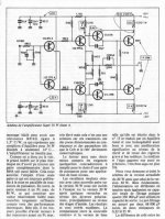
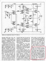
Cause low speed for this amp, not have time to give the necessary current to the load. I have Hiraga 20W (from L'Audiophile '34 jan. 1985). With 0,404F summary filter and 2*160W transformers on high frequencies it has some "metallic overtones" into Martin Logan Electromotion, but with 1,26F filter and 2*300W it's alright.
I've think, that better to do all as an scheme and then "start having fun".
p.s.: I don't like inductors in analog power supply even for digital.
Can you tell me why using 24V 15A SMPS is not good? I put inductor in series with the output and I put 40mF on each rail for each side. So I have 160mF reservoir cap total after the inductor. I don't think this will be in any way inferior to any toroidal supply.
You guys keep talking about ripple and voltage droop. I will not have droop and ripple. I would like to hear a real reason why SMPS is inferior.
Original Hiraga's power supply had 600W+ transformer with filter 0,068F-0R22-0,66F in shoulder. (1,456F summary filter)
Attachments
Cause low speed for this amp, not have time to give the necessary current to the load. I have Hiraga 20W (from L'Audiophile '34 jan. 1985). With 0,404F summary filter and 2*160W transformers on high frequencies it has some "metallic overtones" into Martin Logan Electromotion, but with 1,26F filter and 2*300W it's alright.
I've think, that better to do all as an scheme and then "start having fun".
p.s.: I don't like inductors in analog power supply even for digital.
Can you explain a little more, I am very new to Hiraga. Do you mean the SMPS is too slow to recover from a large current drawn? I thought the SMPS is particular fast as it is charging with 40KHz pulses instead of 120Hz of the normal transformer. Also, it is regulated and 15A. Not to mention it's a Class A, current variation is very small.
The inductor is only a few uH as it's for filtering out the edge of the 40KHz square wave, so it's not going to be in the picture of audio frequency. I think if rock solid rail voltage and fast transient response are what you are after, SMPS should have the advantage over the transformer/rectifier/reservoir combination.
What is summary filter?
Original Hiraga's power supply had 600W+ transformer with filter 0,068F-0R22-0,66F in shoulder. (1,456F summary filter)
I have no idea what you mean
.BTW, do you have the schematic of the original Hiraga amp? I've seen too many different version. I want to built the real thing. Thanks
Last edited:
Can you explain a little more, I am very new to Hiraga. Do you mean the SMPS is too slow to recover from a large current drawn? I thought the SMPS is particular fast as it is charging with 40KHz pulses instead of 120Hz of the normal transformer. Also, it is regulated and 15A. Not to mention it's a Class A, current variation is very small.
The inductor is only a few uH as it's for filtering out the edge of the 40KHz square wave, so it's not going to be in the picture of audio frequency. I think if rock solid rail voltage and fast transient response are what you are after, SMPS should have the advantage over the transformer/rectifier/reservoir combination.
What is summary filter?
2 caps 68000 uF and 0R22 and 4 caps 330000uF - original filter.
I have no idea what you mean
BTW, do you have the schematic of the original Hiraga amp? I've seen too many different version. I want to built the real thing. Thanks
Attachments
Can you explain a little more, I am very new to Hiraga. Do you mean the SMPS is too slow to recover from a large current drawn? I thought the SMPS is particular fast as it is charging with 40KHz pulses instead of 120Hz of the normal transformer. Also, it is regulated and 15A. Not to mention it's a Class A, current variation is very small.
The inductor is only a few uH as it's for filtering out the edge of the 40KHz square wave, so it's not going to be in the picture of audio frequency. I think if rock solid rail voltage and fast transient response are what you are after, SMPS should have the advantage over the transformer/rectifier/reservoir combination.
What is summary filter?
1,456F (2*68000uF+4*330000uF)
- Status
- This old topic is closed. If you want to reopen this topic, contact a moderator using the "Report Post" button.
- Home
- Amplifiers
- Solid State
- Hiraga 20W class A