I built several prototypes of PP amps with GU-50 outputs. I like them a lot. You can't get such quality of sound from 6L6-like tubes, like KT-??, 807, etc... However, it is not the best tube for SE, but compared to 807 in SE it is much better.
Is the last 3rd picture a PSE ?? love that
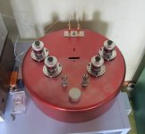
Yes, the last is PSE. Unfinished project.
A right-handed one
Yes.
I like the design, but my OPT won't fit.
You could also try building it MJK-style, but without DC-connection. There is a thread somewhere about it http://www.diyaudio.com/forums/tubes-valves/165221-most-linear-triode-strapped-pentode-7.html#post2204502 . Will probably measure better than the 6E5P but don´t know about sound.
Attachments
Last edited:
Albertli,
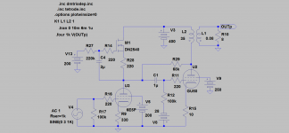
This is a simplified model where your PSU and OPT will work(400V/3,5kohm). Will clip at ca 30V ptp into 8ohm. 6E5P at 200V/12-15mA.
Lars,
Thanks very much. I certainly do make a try on this. I have to digest more before I know how to ask some questions. Hope you would tell me more.
Thanks again
Albert
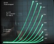
Not sure if of any use here, but was playing today with my curve tracer and did a plot for the GU-50 in triode mode. Unfortunately my anode supply can only swing to 300V at the moment, so curves are limited to that maximum anode voltage.
I took measures from the plot indicating that gm=4.4mA/V, u=4.5 and ra=960. Does it sound about right?
You can download the curves from here:
My Photos
Cheers,
Ale
I took measures from the plot indicating that gm=4.4mA/V, u=4.5 and ra=960. Does it sound about right?
You can download the curves from here:
My Photos
Cheers,
Ale
Attachments
My PSE prototype
This is my PSE prototype - almost finished. B+ 410V, driver ECC801S in SRPP, negative bias (GU50 - around 45mA each), OT 3.5K:8Ohm. Interstage caps: Jantzen Audio Superior 0,22uF. Frequency response from 8Hz - 35Khz 0dB. GU50 in pentode mode - sec grid around 255V. Power >20W/8Ohm.
This is my PSE prototype - almost finished. B+ 410V, driver ECC801S in SRPP, negative bias (GU50 - around 45mA each), OT 3.5K:8Ohm. Interstage caps: Jantzen Audio Superior 0,22uF. Frequency response from 8Hz - 35Khz 0dB. GU50 in pentode mode - sec grid around 255V. Power >20W/8Ohm.
Attachments
Not sure if of any use here, but was playing today with my curve tracer and did a plot for the GU-50 in triode mode. Unfortunately my anode supply can only swing to 300V at the moment, so curves are limited to that maximum anode voltage.
I took measures from the plot indicating that gm=4.4mA/V, u=4.5 and ra=960. Does it sound about right?
You can download the curves from here:
My Photos
Hi Ale;
it would be nice if you show the curves up to +10 Volt on G1. 2 more lines on the picture!
Albertli,
This is a simplified model where your PSU and OPT will work(400V/3,5kohm). Will clip at ca 30V ptp into 8ohm. 6E5P at 200V/12-15mA.
Lars,
I'll make out a psu for your comment.
Do I aim at 100mA tube bias with -28v ??
Albert
Revintage's circuit will work very well.... my circuit is very similar, but my 6E5P run with a simple resistive plate load only. You could run the load as in Revintage's circuit, or with a resistive load or replace the load with a 60-80 Henry choke for the 6E5P.... each will have it's own special sound quality.... try it and pick the one u like the most.
Hi Ale;
it would be nice if you show the curves up to +10 Volt on G1. 2 more lines on the picture!
Hi Anatoly,
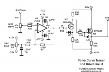
Got only +5v, but strangely enough the +5V is squeezed to the 0V curve. Any idea?
http://www.bartola.co.uk/valves/Construction_gallery/Pages/Traced_curves.html#0
Cheers,
Ale
I thought it was the case, but checked with the oscilloscope and had a perfect step at 5V with no signs of the driver struggling to provide current.
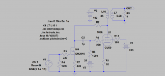
Attached is the driver circuit. with the 10K resistor I think it can't provide more than 1ma there...
Any suggestions?
Thanks
Ale
Attached is the driver circuit. with the 10K resistor I think it can't provide more than 1ma there...
Any suggestions?
Thanks
Ale
Attachments
Revintage's circuit will work very well.... my circuit is very similar, but my 6E5P run with a simple resistive plate load only. You could run the load as in Revintage's circuit, or with a resistive load or replace the load with a 60-80 Henry choke for the 6E5P.... each will have it's own special sound quality.... try it and pick the one u like the most.
Thanks and would love to try all those you recommend. I thought I'd start doing it as of Lars design. I'm making the wood chassis and would cut the aluminum top plate sometime next week.
Albert
- Status
- This old topic is closed. If you want to reopen this topic, contact a moderator using the "Report Post" button.
- Home
- Amplifiers
- Tubes / Valves
- Help with these Russian GU50 tube amplifier