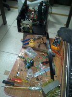
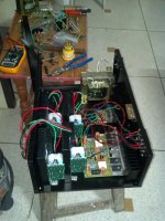
I left the amp turned on during night with some music playing on very minor volume just to make sure that the chips aren't getting hot during long usage. Then I played some music in loud volumes and its playing fine.
The transformer 24-0-24 was feeding all the 5 LM3886 boards and the 200W sub board. Now my question is why do I need separate transformer if the single 24-0-24 is doing the job fine? The performance is acceptable so far.
Second transformer I have is a 23-0-23 with an additional 18-0-18 tapping which I got for sub crossover and I think I can skip that crossover since my compute can control the sub. Using second transformer means separate PSU and more space requirement and it will weigh lot more. If I can keep the single transformer than I can think to bind all the stuffs together in one single cabinet.
Please share your suggestions on it.
Guys. please share your opinion on the above and also help me sorting out these issues:
1. The usual humming and hissing noise issue which I was facing earlier has gone and when I turn on the 5XLM3886, they don't give hint like something is turned on. But when I tried to observe the noise by by putting my ear near to the driver, minor kirrrr kind of noise was present there and a very-very mild hum was also there. It is very-very minor and doesn't interfere while listening audio and doesn't feel at usual sitting position but I would like to delete it as well.
2. My sub makes my sub driver to pop out loudly when it is turned on which will damage the driver sooner or later, I have a speaker protection module which I tried to add between the amp and the speaker but it didn't work. The cone pop out effect wasn't there but sound also got muted, no audio signal was passing through. I checked the volts and those were fine. This is the module I have:
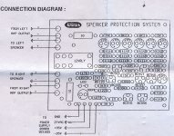
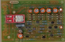
Whats maybe the problem? I checked the connection and those were according to the diagram and the markings given on the board.
Is there is some other easier solution to protect the driver?
3. Due to odd size of the heatsinks, I had to dump the old idea of the amp cabinet and now thinking about this simpler 2-piece thing:
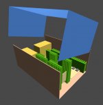
Total dimensions of the cabinet : (W)430mm X (L)300mm X (H)180mm
It can accommodate - 5X3886, 1Xsub amp, 2Xtransformers, 2XPSU circuits on one board, and some other added modules by making some arrangements.
Last edited:
Check the relay. Does it get energized when you turn on the device.
You must be hearing some clicking noise of the relay. If not there is some issue with the circuit.
Check the voltage across relay it should be close to 12v. Double check the wiring.
The circuit has a "loss of ac detector" you need to connect the ac output of your transformer. I.e before the rectifier to the circuit.hope you must have done the same. Post pics of the wiring lets see the same.
To test the DC speaker protection disconnect the speaker output from the Protection circuit but keep the power supply connected to the protection circuit , Then connect a DC power source of say 3v-5v (Maybe 2 or 3 AA batteries in series) to the speaker inputs on the Protection circuit and listen for the Relay to Switch , you should hear it click every time the DC is connected to the Protection circuit .....
Generally speaking the loud pop you hear when you turn on the power isn't going to hurt your speaker , it is generally a extremely short DC burst to your speaker which isn't enough to harm the voice coil , though the Protection circuit is very useful for protecting your speaker in case of some sort of chip failure and clipping ... Many times when a chip fails it will output half the supply rail to the output which will fry your speaker in about 15 seconds ....
Generally speaking the loud pop you hear when you turn on the power isn't going to hurt your speaker , it is generally a extremely short DC burst to your speaker which isn't enough to harm the voice coil , though the Protection circuit is very useful for protecting your speaker in case of some sort of chip failure and clipping ... Many times when a chip fails it will output half the supply rail to the output which will fry your speaker in about 15 seconds ....
The diagram has marking for +/-37v, ground and ac inputs. I connected ground form rectifier to ground and +/- 27 after rectifier to the +/- of he circuit. Then connected amp and speaker lines to the circuit.Check the relay. Does it get energized when you turn on the device.
You must be hearing some clicking noise of the relay. If not there is some issue with the circuit.
Check the voltage across relay it should be close to 12v. Double check the wiring.
The circuit has a "loss of ac detector" you need to connect the ac output of your transformer. I.e before the rectifier to the circuit.hope you must have done the same. Post pics of the wiring lets see the same.
Now you say i should connect the AC. There is only one point for AC line, then doesn't it mean that I should connect one of the 24v supply from tranny to the AC line and the (0) to the ground? Please see the diagram of the circuit I posted in my earlier post and help me out understanding the connection.
Hmmm... Didn't think about that. Then what is better fail safe alternative.though the Protection circuit is very useful for protecting your speaker in case of some sort of chip failure and clipping ... Many times when a chip fails it will output half the supply rail to the output which will fry your speaker in about 15 seconds ....
When I start the amp, the sub driver's cone come out with a loud sound, it just feels scarey and makes me worried, its not normal pop out sound, its too loud.
Last edited:
As you are saying you have already connected the dc supplies of +-37v to the board and the ground connection aswell. You just need to connect any one of the tranny's secondary ac output to the ac input of the board, ensuring the ac is not above 27volts. Leaving this connection will not allow the circuit to work. The circuit encorporates a delay network of capacitors and transistors, whenever the circuit will detect the ac signal from transformer it will energize the relay after a short span of time (delay) depending upon the value of the capacitor. This will prevent any switch on thummps arising due to transients. The role of the circuit here is that it will connect the speaker to the amp through the relay after a short period of time where in the amplifier circuit has been stabilized and there are no dc offsets or transients at the output. And immediately when the power is removed the ac signal is lost which will instantly swtich off the transistors driving the relay. And the speaker terminals are shorted to ground . Thus elimanting switch off sounds if any. This will protect your speaker from excessive excursion, and mechanical failure of the driver.
Also as a suggestion use a subsonic filter with this filter which will protect the driver from excessive excursion below 18hz.
secondly dont use the same psu to supply all amps. Built seperate psu for all channels. This will eliminate cross channel interference. I will suggest building a seperate psu for your sub with its dedicated trafo. Also better to use several filter caps in parallel rather than one single high value capacitor. For example ..better to put 4 pcs 4700uf capacitance in parallel than using one single 22000uf capacitor. This will handle transients in sound much more faster than one single cap. As bigger caps will take more time to charge.
Hope you will find it helpful...
Thanks saraswat, that is indeed helpful So you mean I will have to connect AC from transformer along with ground and +/- supplies? So total for power inputs need to be connected there? I thought either use AC or DC.
About the separate PSU for each channel, I think that won't be feasible/practical here, that will need lot of space for each PSU since there will be 5 + 1 PSU for 6 channels. Though can build a separate PSU for sub and I have few items ready with me for that - 2X10000uf caps, 35A bridge rectifier, 2X0.1uf.
About the separate PSU for each channel, I think that won't be feasible/practical here, that will need lot of space for each PSU since there will be 5 + 1 PSU for 6 channels. Though can build a separate PSU for sub and I have few items ready with me for that - 2X10000uf caps, 35A bridge rectifier, 2X0.1uf.
Last edited:
Yes you are right now. You have to connect all ac and dc inputs together. I.e all 4 together.
Atleast keep two seperate psu for left and right channel. One for subwoofer and built another for remaining channels. This is bare necessary. You can have everything in a very compact space if you design it properly.
Will share some of my amp pics. You will get an idea.
Atleast keep two seperate psu for left and right channel. One for subwoofer and built another for remaining channels. This is bare necessary. You can have everything in a very compact space if you design it properly.
Will share some of my amp pics. You will get an idea.
Thanks saraswat, will try the speaker protection module again tonigh and will report back. 
I also have a readymade PSU which takes multiple input and outputs but that got fried during my testings. Will try to fix that by replacing fried caps and will also replace few caps and the bridge rectifier with higher ratings. If that starts working back then that can be used for my sub+crossover.
The one I already made can be used for rear+center channels. and I can think about separate PSU for front left and right.
Waiting for your ideas with pics so that I can plan how can I fit them in the limited space of the cabinet.
BTW is it necessary to use separate transformer for the SUB? Right now all of the amps are running through single 24-0-24 transformer and I didn't notice any degradation in sound quality.
The cabinet I am thinking is a packed type and I am thinking of using one fan in the cabinet, I have a fan which I removed form a computer SMPS, how much power supply does it need? If I use a single transformer for all the amps then I can put a smaller transformer if that is required to feed the fan. I have few small transformers rated between 9v to 12v but those have only two supplies, there isn't any ground in them.
Last edited:
BTW is it necessary to use separate transformer for the SUB? Right now all of the amps are running through single 24-0-24 transformer and I didn't notice any degradation in sound quality.
To get power from amplifier one have to give it too..
Have you connected lowpass filter and sub-woofer drive with your sub Amp...?
To drive low frequencies properly you will need good power from PSU.. so use separate transformer for sub-amp.
Yes..yes, I will use separate transformer + PSU for the sub, I even observed some disturbance signals in the tweeter-speakers during bass passing through the sub so atleast sub should be separate.To get power from amplifier one have to give it too..
Have you connected lowpass filter and sub-woofer drive with your sub Amp...?
To drive low frequencies properly you will need good power from PSU.. so use separate transformer for sub-amp.
But right now I want to sort out the speaker protection issue
Couldn't try that with AC power, will see if I can test that tomorrow.
Also got built the cabinet from a sheet metal. so not I will start assembling all the components in the cabinet also.
Here I have one doubt that audio-video input jack for inputs, and the outer metal part of those jacks will be touching the cabinet. Similarly there are many components where base part of those components will be touching the metal and all of them will be combined with each other.
What precautions I should take care here?
After digging a lot on internet, could find one source:
Buy HeatSinks for amplifier at low prices in India, online.
They have one heatsink with dimensions of 196/100/33mm with Rth 0.6 K/W rating. Can I use this heatsink to cool down two LM3886 chips? I know Andrew is feeling like kicking me from behindwhile I am talking about this but is that gonna become really that risky or I can try out this first and can add more heatsinks later if I face any issue?
Also, do I need to put a thick aluminum or copper spacer between the chip and the heatsink?
Nobody would feel to kick other in DIyer's world.But if you repeat same mistakes ignoring advices,yes there are chances.
AndrewT is one among the best personalites around
Thanks saraswat, will try the speaker protection module again tonigh and will report back.
I also have a readymade PSU which takes multiple input and outputs but that got fried during my testings. Will try to fix that by replacing fried caps and will also replace few caps and the bridge rectifier with higher ratings. If that starts working back then that can be used for my sub+crossover.
The one I already made can be used for rear+center channels. and I can think about separate PSU for front left and right.
Waiting for your ideas with pics so that I can plan how can I fit them in the limited space of the cabinet.
BTW is it necessary to use separate transformer for the SUB? Right now all of the amps are running through single 24-0-24 transformer and I didn't notice any degradation in sound quality.
The cabinet I am thinking is a packed type and I am thinking of using one fan in the cabinet, I have a fan which I removed form a computer SMPS, how much power supply does it need? If I use a single transformer for all the amps then I can put a smaller transformer if that is required to feed the fan. I have few small transformers rated between 9v to 12v but those have only two supplies, there isn't any ground in them.
Amp pics
An externally hosted image should be here but it was not working when we last tested it.
An externally hosted image should be here but it was not working when we last tested it.
An externally hosted image should be here but it was not working when we last tested it.
An externally hosted image should be here but it was not working when we last tested it.
An externally hosted image should be here but it was not working when we last tested it.
Yeah, I couldn't go over his recommendation on the heatsinks and got really big heatsinks separate for each chip as he and other fellows suggested and now I feel it was worthAndrewT is one among the best personalites around.
Thanks for the pics saraswat, got some ideas now.Amp pics
Last edited:
Hey find your fan psu schematics from your available transformers without centre tap.follow the diagram and built your own on some vero board. Diodes are 1n4007. Capacitor can be 2200uf 25v.
Computer fans are normally 12volts and u can use your 9 volts transformer To power the same. You can use multiple fans in series or parallel connections from the same psu. Parallel will be bette if supply voltage is within 12volts. If higher then use series connection of fans.
Use fans above the heat sink to blow the heat sinks. That will be more useful rather than putting fans in cabinets. When you sip hot soup from spoon you blow the spoon to make it cool rather than suckng air around. Putting fans in cabinets will do the later which is not effective in cooling. Hope u understand and choice is yours.
An externally hosted image should be here but it was not working when we last tested it.
My suggestion was that you use the information in the National datasheet and apply it to your operational temperatures.I couldn't go over his recommendation on the heatsinks and got really big heatsinks separate for each chip as he and other fellows suggested and now I feel it was worth.
If you choose to run the chip near maximum outputs with their standard recommendation for heatsink, the protections will be repeatedly and frequently operating.
I recommend that you then double the National size so that your chip is operating at junction temperatures way below the 125°C to 150°C that National use for their calculations.
BTW,
I have little in the way of personality. And I don't even qualify as a geek.
Need suggestion on fuse rating.
Right now I will be using one power socket for all transformers but separate on/off power switches. Can I use one single fuse before them? What rating should it be? I have 2A and 3A fuses with me and installed a fuse box in the cabinet.
I will also add fuses after DC in +/- lines. What rating should be that?
Main transformers are :
24-0-24, 10A
23-0-23, 8A with 18-0-18 tapping for sub crossover.
I may use another small transformer if I plan to add fans in the cabinet and the 18-0-18 doesn't work for them.
BTW do I need additional power supply circuit for the crossover? the power rating for the crossover is 18-0-18 and the rectifiers will increase the power which I don't need here since transformer itself has 18-0-18 supply.
That transformer in the picture ,from the looks is 1.75 inch core which may not provide yo with more than 150watts of total power.
going by Power=VxI....
going by Power=VxI....
Need suggestion on fuse rating.
Right now I will be using one power socket for all transformers but separate on/off power switches. Can I use one single fuse before them? What rating should it be? I have 2A and 3A fuses with me and installed a fuse box in the cabinet.
I will also add fuses after DC in +/- lines. What rating should be that?
Main transformers are :
24-0-24, 10A
23-0-23, 8A with 18-0-18 tapping for sub crossover.
I may use another small transformer if I plan to add fans in the cabinet and the 18-0-18 doesn't work for them.
BTW do I need additional power supply circuit for the crossover? the power rating for the crossover is 18-0-18 and the rectifiers will increase the power which I don't need here since transformer itself has 18-0-18 supply.
- Status
- This old topic is closed. If you want to reopen this topic, contact a moderator using the "Report Post" button.
- Home
- Amplifiers
- Chip Amps
- Help Needed on DIY LM3886 based 5.1 Channel AMP for PC Home Theater
