But that leads into turning the AMP cabinet size too bigi would not. one chip pr sink will work fine.
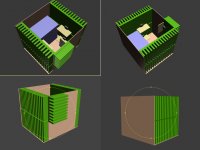
Well there is one arrangement - one heatsink above another. By doing this, total height of heatsink turns out into 200mm and length remains same 196mm. Total dimension of cabinet turns out into 230 (W) X 200 (L) X 200 (H) mm (approx). Yeah, I may have to increase the total area by a little more but this is something what I can look out with this heatsink option. How is that?
Here is a 3D illustration of the above I just created:
But the cost is too much for this heatsink. I can arrange four pentium-III heatsink+fans in the cost of one heatsink
There is another thought if I want to use the single heatsink, I don't put the two LM3886 in row or parallel, rather I put them in unsymmetrical way like this:
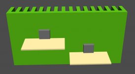
Shouldn't this increase the cooling efficiency since more heat is built up there near the chip itself and by doing the above arrangement, we are actually increasing the distance between the two chips yet maintaining maximum free surrounding area ?
Last edited:
as Andrew said. reduce the voltage or increase the speaker impedance. and ad a A/C unit in your livingroom, so that ambient is steady at max 25c. then you i'll get away with much less.
i'm going for one single 0.4C/W heatsink for my 5ch LM3886 + 1 Hypex UcD400.
with +/-25V on 4ohm speakers and 20C ambient that is all that is needed.
i'm going for one single 0.4C/W heatsink for my 5ch LM3886 + 1 Hypex UcD400.
with +/-25V on 4ohm speakers and 20C ambient that is all that is needed.
Last edited:
Finally ordered four of these: Heat Sink - SE 201-160
201mm (L) x160mm (W)x 25 mm (H).
No info on rating but these are bigger compared to earlier considered heatsinks so these should be more cooler.
Now I can plan something like this:
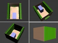
Total inner space available is around 220W X 320L X 200H mm (8.6" X 13" X 7.8").
It has little bit more space inside to move the hand while working on it and can easily accommodate some extra stuffs like PSU and some other stuffs in case of upgradation or additions.
201mm (L) x160mm (W)x 25 mm (H).
No info on rating but these are bigger compared to earlier considered heatsinks so these should be more cooler.
Now I can plan something like this:

Total inner space available is around 220W X 320L X 200H mm (8.6" X 13" X 7.8").
It has little bit more space inside to move the hand while working on it and can easily accommodate some extra stuffs like PSU and some other stuffs in case of upgradation or additions.
You mean the one attached at the rear of the cabinet? Okay, have fixed it in the above design.The upper pic shows one sink lying on it's side. This will make that sink and the device attached run hotter.
Last edited:
Thanks Mihkus for your inputs.
Now I need some help on constructing the sub amp to final stage.
I have a 200W Toshiba 2SA1943/2SC5200 amp board. Its output rating is said 200W RMS @ 8 ohm load and power supply needed is 2 x 30-42VDC / 520-720VA (according to the supplier).
I will be using this board with a 4ohm driver and got a transformer with rating of 23-0-23, 8A. So rectified volts should be somewhere near to +/-30v (kept on lower side considering the 4ohm load). This transformer also has a tapping of 18-0-18 which I got for the subwoofer crossover which needs this power output.
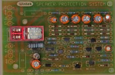
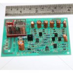
I also have a speaker protection module which I want to use with the sub amp. Now there are 3 components which will be fitted in the sub amp cabinet. But I am not sure how to distribute the power supply through that transformer to these components.
I bought a PSU with multiple input/outputs with different ratings but that PSU got fried during my past tests with the transformers. Lot of caps have burnt in that PSU.
Right now I have a set of these:
10000uf/63v = 2
01uf = 2
35A bridge rectifier = 1
I can build this PSU for main sub amp but what I need for carrying the 18-0-18 supply into sub crossover?
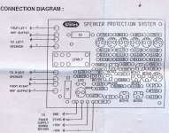
Also how to take power supply into speaker protection module from the same transformer?
Here are pictures and connection diagram of the speaker protection module:


Check the rating yourself...........Its output rating is said 200W RMS @ 8 ohm load and power supply needed is 2 x 30-42VDC / 520-720VA (according to the supplier)..............
You will soon realise the retailer is lying !!!!!!
Learn to recognise the wheat from the chaff.
200W into 8r0 (a resistor test load) requires an output of 40Vac.
This is equivalent to 56.6Vpk and 7.1Apk
Expect the loss from PSU to load to be around 3Volts to 8Volts.
Expect the PSU to sag by around 2Volts to 10Volts.
Expect the ripple on the rails to be around 1Volt to 3Volts.
To get that 56.6Vpk at the load the amplifier needs to see at least 59.6Vdc (loaded) and maybe as much as 64.6Vdc (loaded).
Add on half the ripple to get average amplifier voltage. This gives 60.1Vdc to 66.1Vdc average loaded supply voltage.
Add on the PSU sag to those supply values. You are now up around +-62.1Vdc to +-76.1Vdc to meet that 200W into 8r0 specification.
Aim for +-68Vdc to hit a 200W target.
If you cannot check for unscrupulous suppliers then you have little hope of achieving your targets.
Last edited:
But that is for 8ohms load, what about 4ohm? There isn't anything mentioned by the retailer about 4ohms. And I am looking for something near to 160W since my driver is 160W rated.Aim for +-68Vdc to hit a 200W target.
Anyways also bought a screwdriver-cum-drill machine with few bits. The machine has few selective speeds and has reversible action as well but isn't that powerful since it also serves as a screw driver, hope it does the job for me. I am diving bit deeper in the DIYs and collecting lot of tools these days.
Last edited:
I think you would never need that much cooling... I got 3 3886 chips in parallel attached to 1,6W/C░ and it warms up just a bit... at 4R -+40V
That heatsink at the back is useless id say... but massive cooling is healthy for SpiKe
i'll say that a 1.6C/W sink is useless for 3 chips. unless they are inside a fridge.
also. +/-40V and 4ohm load is useless. all you get is excess of heat at idle.
the bias is what the bias is. max usefull rail voltage for 4 ohm is +/-28V
so 24V * bias of excessive heat pr chip.
A minor update:
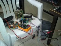
My heatsinks are still on the way so today I decided to play the existing LM3886 along with the sub amp. I attached both the amps with my 24-0-24 transformer+PSU and allowed both the amps play for a long time. Both of them seem to playing nice with the single transformer. I measured the volts on both amps and it was showing around 25.6v on both amps. I checked while played loud and also when there wasn't any load.
Is there any way that I can measure clippings or drop in power?
Also how to measure ohms form multimeter? I set the dial on ohms and measured both +/- points of the speaker outputs. Measurement was varying but it was also dropping till '1' on some occasions. Even it was dropping till 0.2/0.3 when there wasn't any audio signal. Is that correct way to measure or I am missing something?
Any other measurement where I should keep eye during initial days testings?
About the heatsink, I feel the investment is worth. I was testing one LM3886 amp kit which came with preinstalled heatsink and the chip was getting warmer (not hot) whereas the Toshiba amp kit remained cool which has a bigger heatsink.
I didn't dare to test my rest of four LM3886 kits since those don't have the heatsinks. Now waiting for the heatsinks and will build a box.
Last edited:
Is it necessary to put that aluminum piece between the chip and the heatsink as shown in the picture below:
View attachment 376069
No
Here comes the another problem. The heatsinks I got aren't amtching the claimed size of 200X160mm, rahter they are just 160X88mm.
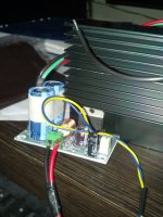
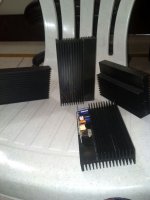
Another thing, the heatsinks have fins on both sides and there is very little space available to attach the chip and my LM3886 board with Rubycon caps isn't fitting in that space.
Can I attach the chips like shown in the image below or in any other way or there is only one set format to attach the chips for maximum cooling performance:
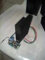


Another thing, the heatsinks have fins on both sides and there is very little space available to attach the chip and my LM3886 board with Rubycon caps isn't fitting in that space.

Can I attach the chips like shown in the image below or in any other way or there is only one set format to attach the chips for maximum cooling performance:

Last edited:
Finally all of 6 channels are playing 
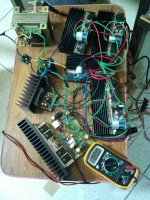
Got cut few of the fins from the heatsinks and attached chips to them. Connected all of them including sub amp to the 24-0-24 transformer and started playing. Everything is running fine.
Sub amp makes loud sound when turned on so I will need to add speaker protection to it.
Now time for some exercise on cabinet building.
- Status
- This old topic is closed. If you want to reopen this topic, contact a moderator using the "Report Post" button.
- Home
- Amplifiers
- Chip Amps
- Help Needed on DIY LM3886 based 5.1 Channel AMP for PC Home Theater
![LM3886_4-500x500[1].jpg LM3886_4-500x500[1].jpg](https://www.diyaudio.com/community/data/attachments/341/341635-265ee9f08c8c869f8d85c90bc5b296f6.jpg)