ilimzn said:PNP transistors alow bolting directly to a negative ground chasis (in a car, say). The lack of bias suggests the circuit may have originally been developed for germanium power transistors (and here PNPs were also more abundant).
in fact they were, 2sb449 comes to mind...there is a resistor string that biases the output trannies somewhat...

found an old organ amp (Rogers) on the "parts beast" shelf, has a pair of 2N2081 output devices in it. since it's on the "parts beast" shelf, i don't think the amp works, but if anybody is interested in the transistors, i can make the time to test them. they are PNP germaniums from Motorola, 45Vceo, 16A Ic, 35 Hfe. now i remember one of the reasons we don't use Ge output devices anymore..... they have an Ft of a whopping 5kHz.....
The heck with the output transformer, just use a DVC woofer, darlington outputs, and a pair of diodes for bias.
"targa" dual voice soils speakers are avaialable in manila, maybe worth while to try...
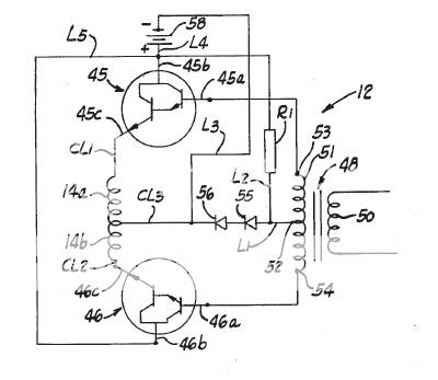
for those who wish to diy, the input transformer is wound from EI- 1/2 in center leg, square cross section, bobbins are available. primary turns of 64 and #24awg magnet wire, secondaries two coils of 150 turns # 28awg magnet wire.
hi denver,
i'd like to call that the old faithful..that was similar to my first booster back when i was 16..
try using valiant vt65 (still available here in cebu) or other bigger input transformer instead of the usual #21input transformer,also use a driver ic that can load down to 2R..
i have higher power versions running on 12-36v without changing the bias..
hi longthrow,
could you perhaps post schemes for your version
well, basta Sugbo-anon bisan pag back to back
nya bihagay di malupig!
well I am still very interested with this circuit specially
driving it with 24volts powersupply.
I once stumbled with a paper drawn with a schematic and a saying that says:
" templa_templa sa Sugbo"
macweb


yep, that's the standard late '50s, early 60's xfmr coupled output stage...... used by zenith, rca, motorola, etc in all of their console stereos. about 5%THD at rated power. sounds horrible when clipped from magnetic as well as transistor saturation. one advantage over the tube version of this circuit was that the xfmr didn't have to be insulated for hundreds of volts. since you're driving an inductive load, i would add flyback diodes across the C-E lines on the transistors to protect the transistors from inductive kick.
booster Post #54 hienrich, i thought ill just post the schematic now,while i still have time. what do you think of this one?....
hi longthrow,
pretty smart idea huh...
actually I've tried this one before.
darlington connected for enhanced beta for the final
outputs. yet also changing values of the 5watt resistors
for it bias voltages.
longthrow if ever just mail them to me.
email ad: hienrichb at yahoo dot com
thanks in advance,
macweb
well the trick is not to change the bias resistors when you change the supply...
the two diodes in series limits the dc base current so that voltages ranging from 12-36v wont damage the transistors..since we vary the max power output through the supply (Vce that is )..
the power required to drive the input transformer is minimized,also the darlington configuration allows you to add more power tranies without much (negligible) loading on the input secondary,therefore higher voltage swing is achieved as compared to the conventional (old) circuit where the sec. directly drives the power output tranies lets say ummmh 6-10 pairs or more? some "technicians" even go as far as 50pairs! (100total) for just a single channel..
thats the usual practice here...
but of course i dont do that!!.
ill post some pics in time..
hi tony,
they did use 2955,(pretty cheap PhP 18-30) & the usual practice here, the total base drive current is around 6-10 mA...all that current is to be consumed by 100 tranies without the emitter stabilizers!!...as a result, 1,2 or more (but not all) heats up when supply is increased to 24-36v..
to most of them here,they neglect the idle current (not aware of it when tranies are warm even when idle)..
in my version,aside from darlington configuration, i did use emitter resistors & to 247 power pnps 4-8 pairs (for easy mounting, not MJ2955s), depending on how much the load impedance will be...
depending on the type & number of output tranies,the idle current does not exceed 100mA,
- Status
- This old topic is closed. If you want to reopen this topic, contact a moderator using the "Report Post" button.
- Home
- Amplifiers
- Solid State
- hello, how about this booster for amplifier