lumanauw said:Hi, Mike,
This is the cap multiplier. Q14 and Q15. It multiplies the cap by HFE value, because the only thing that is attached to the base is cap and small current leakage from R for turning the Q on. It gives very clean +/-rail for front ends. The R and C makes a lowpass filtered that is injected to base.
Mike, I really looking forward your "invesgation report" on 8 Transistor design transformed to your design. Step by step. What every single change makes on the sound. Like R vs CCS, current mirror (not every body likes it), single / triple darlington output etc. Maybe the format is something like peufeu website reported?
Scopes are not that expensive. You can go to local electronic market, usually there are used ones for fair price. Low MHZ are OK, not need high-end scopes for audio (except you want to examine RF modulation on audio tracks)
Hi lumanauw,
please note that for proper working of capacitor multiplier, we need to drop some voltages across the transistor. So You have to design the resistor, to drop little more voltage than the ripple before the multiplier, and the saturation voltage of the transistor.
1.5-2V looks OK.
If You don't allow enough voltage the stage will saturate, and there will be no proper working.
sajti
21V output voltage ,gain=10k/330 =33MikeB said:hi thanh !
Hmm, with 700mv inputvoltage my amp is far above clipping...
Which outputvoltage does this input result ?
I choosed 300mv, as this is already "high" power, but not too near
to clipping. And typically ~14volt output is already 25watt rms for me,
(have 4ohm boxes) and that's already unacceptable volumelevel.
(For my neighbors at least) My speakers have ~90db/W...
Mike
"Have you ever succeed in buiding a input stage with current mirror?"
Yesss !
http://web.interware.hu/kontor/cortez/kepek/CA1.jpg
http://web.interware.hu/kontor/cortez/kepek/CA2.jpg
I'am just testing it...! Lux like not bad !
(constant P @ inputstage + cascoded VAS + VAS buffer + CFP output stage)
Yesss !
http://web.interware.hu/kontor/cortez/kepek/CA1.jpg
http://web.interware.hu/kontor/cortez/kepek/CA2.jpg
I'am just testing it...! Lux like not bad !
(constant P @ inputstage + cascoded VAS + VAS buffer + CFP output stage)
Hi, Sajti,
Thanks for the info. I made cap multiplier with 1k resistor + 22uF cap. I measured Vce is only 0.9V Is this too low? You suggested 1.5-2V drop. Is this for the Vce?
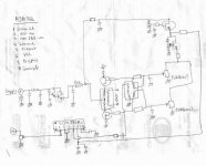
This is another example of cap multiplier. The amplifier itself is a non-feedback, transformer output (Jensen) SS amp. The sound is marvelous, but it needs clean supply, so the designer put a Darlington for cap multiplier.
The cap multiplier darlington is made by C5200, driven by BD139.
The designer put Darlington so he can get low drop while needed big current for the audio amp?
This amp sounds very good. Is it due to the very few transistor passed by the audio signal (minimum stages phylosophy)? I believe the distortions are big due to non feedback and transformer output. But it really sounds nice.
This is another example of "Sound VS Distortion" besides Single Ended Triode (SET) amplifier.
Thanks for the info. I made cap multiplier with 1k resistor + 22uF cap. I measured Vce is only 0.9V Is this too low? You suggested 1.5-2V drop. Is this for the Vce?
This is another example of cap multiplier. The amplifier itself is a non-feedback, transformer output (Jensen) SS amp. The sound is marvelous, but it needs clean supply, so the designer put a Darlington for cap multiplier.
The cap multiplier darlington is made by C5200, driven by BD139.
The designer put Darlington so he can get low drop while needed big current for the audio amp?
This amp sounds very good. Is it due to the very few transistor passed by the audio signal (minimum stages phylosophy)? I believe the distortions are big due to non feedback and transformer output. But it really sounds nice.
This is another example of "Sound VS Distortion" besides Single Ended Triode (SET) amplifier.
Attachments
Hi guys !
Thanks for the info on cap-multiplier !
I only used a 47uF + 22ohm for stabilizing, according to
sim this was enough to get stable supply for the frontend.
It definitely changed the sound.
I will check with the capmultiplier !
Cortez, already any statement on sounding of your amp ?
to thanh: with 24volt supply its hard for my amp to deliver 21v...
I use a gain of 1:45.
Mike
lumanauw said:Hi, Sajti,
Thanks for the info. I made cap multiplier with 1k resistor + 22uF cap. I measured Vce is only 0.9V Is this too low? You suggested 1.5-2V drop. Is this for the Vce?
This is another example of cap multiplier. The amplifier itself is a non-feedback, transformer output (Jensen) SS amp. The sound is marvelous, but it needs clean supply, so the designer put a Darlington for cap multiplier.
The cap multiplier darlington is made by C5200, driven by BD139.
The designer put Darlington so he can get low drop while needed big current for the audio amp?
This amp sounds very good. Is it due to the very few transistor passed by the audio signal (minimum stages phylosophy)? I believe the distortions are big due to non feedback and transformer output. But it really sounds nice.
This is another example of "Sound VS Distortion" besides Single Ended Triode (SET) amplifier.
Hi,
I suggest the 1.5-2V, but of course it depends the load, and the ripple on the line. It's easy to imagine: The capacitor keeps constant voltage. At the input of the multiplier (collector of the pass transistor) You can measure the ripple voltage, which is AC over the DC. If thi ripple makes the input voltage of the multiplier less than the voltage in the capacitor, the CB diode in the transistor will open, and this will results drop in the output.
Another thing I use for the cap multiplier is 100ohm basestopper resistor. This is just to avoid oscillation.
0.9V Vce can be enough, if the load is just few mA, and there is no more ripple than 2-300mV over the input DC voltage. I would increase the series resistor to 2.2kohm, which will results approx 1V Vce.
sajti
Not bad ! But i have to build an other amp too (for stereo testing...) !MikeB said:Cortez, already any statement on sounding of your amp ?
MikeB said:Hi guys !
Thanks for the info on cap-multiplier !
I only used a 47uF + 22ohm for stabilizing, according to
sim this was enough to get stable supply for the frontend.
It definitely changed the sound.
I will check with the capmultiplier !
Cortez, already any statement on sounding of your amp ?
to thanh: with 24volt supply its hard for my amp to deliver 21v...
I use a gain of 1:45.
Mike
H Mike,
22ohm+47uF looks good. I use 10-22ohms, and 1000uF and series diode. This means that when the output current pull down the rails the 1000uF capacitor keeps the supply voltage for the driver stages. I use this filtered voltage only for the signal stages. I not connect the ccs supply, and the DC servo to this filter. With this I can keep the voltage higher, which means more output with same rail voltage. (Separated rectifier, and filter capacitors could be much better!)
If You keep the existing filter, add 100-470nF kapacitors paralell with the filter cap. This helps to keep low impedance for the driver stages especially in the higher frequency range.
Get 21V peak output from 24V rail is not so diffiult. Just add small voltage gain for the CFP stage. 1.1 is enough.
sajti
Hi, Mike,
If I got 3 current mirror variations : Signal is put into left Q and output is right Q.
A. A current mirror with 100ohm for left RE and 300ohm for right RE (gain=3)
B. A current mirror with 300ohm for left RE and 300ohm for right RE (gain=1)
C. A current mirror with 300ohm for left RE and 100ohm for right RE (gain=1/3)
Will those 3 exhibit different harmonic pattern? Which has the lowest thd? Or they all have the same thd?
Hi sajti !
Yes i putted 100nF in paralell to the electrolytics, to make sure
that the compensation does not degenerate too much for high
frequencies. I skipped the diodes for not loosing too much
voltage.
As i use tripledarlington-EF, the amp clips at ~20.5v.
Hi lumanauw !
I am bit confused, are you talking about the currentmirror at diffamp-
output ? Typically these RE's need to be identical ?
Mike
MikeB said:Hi sajti !
Yes i putted 100nF in paralell to the electrolytics, to make sure
that the compensation does not degenerate too much for high
frequencies. I skipped the diodes for not loosing too much
voltage.
As i use tripledarlington-EF, the amp clips at ~20.5v.
Hi lumanauw !
I am bit confused, are you talking about the currentmirror at diffamp-
output ? Typically these RE's need to be identical ?
Mike
Sorry Mike! I don't know why I remember to CFB output?????
sajti
lumanauw said:Hi, Mike,
It is not for differential legs, but for VAS. Connecting one leg of differential, the other is VAS.
I wonder if it is ok to make VAS with gain, with no gain, or with gain less than 1. Usually VAS always have gain. Maybe we can find something of this VAS gain.
Ah, i understand. Are we talking about symetrical or ccs-loaded vas ?
Re's don't have much impact on gain in the vas. The gain for a ccs-driven
or symetrical vas is very high (> 1:5000) and can only really reduced
with R-loading. This means you put 2 resistors from the Vbe inside
the vas to ground. These must not be too big, or gain drops below
a level necessary for full voltageswing. The minsize of these resistors
depends on the currentbias of the vas.
My experience with identical RE's was a lower DC-offset.
For the case i misunderstood you, can you show a schematic ?
(A ccs-driven or symetrical vas is also some kind of currentmirror)
Mike
Hi, Mike,
This is example of what I intended to do. It is from the sch submitted by Thanh. Look at Q1 and Q7. If I make both RE resistor 390ohm, wouldn't it perform a VAS that has no current gain? Because the current entering Q1 will be the same as the current leaving Q7 if both RE are the same value?
In the original sch, the current gain in VAS (toward current in differential leg) is 1K8/390.
Attachments
Hi lumanauw !
You're confusing me, VAS is a voltageamplification, means you should
look at voltagegain not currentgain. The 1.8k to gnd set the gain
for the vas, Q1/Q4 are only diodes. If you change the 1.8k at q1, you
also change the biascurrent in vas, so is the 390ohm.
Q1 is for increasing bias, without increasing gain.
As this is a symetrical vas, you should keep values symetrical, or you
get large dc-offset.
Mike
Hi, Mike,
Now I'm confused too
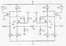
The story is like this. With CFP differential, I can make very big current passing thru the differential pair. I can make 20mA ccs differential (10ma to each leg), without ruining the sound.
I get the idea from Susy by Nelson Pass. He stated that Differential+folded cascode maybe considered 1 stage only (I think because the Folded cascode VAS doesnt have current gain).
The items 21+31 or 20+30 are 1 stage. Item 20 and 21 is differential.
I want to make variation of this cct, but only half. Making a differential with big bias + vas that has no current gain, so the both of them can be considered 1 stage only.
I wanted to try the "minimum stage" Phylosophy, since from my experiments, it do tends to get better sound.
Since I wanted to advoid class A, the only way to make 2 stage class AB power amp is with differential+current mirror VAS or differential + folded cascode VAS (VAS that does not have current gain, the current=current in 1 leg of differential).
I think making configuration like this will have excellent stability properties, because all the current gain is happening in the differential only.
Now I'm confused too
The story is like this. With CFP differential, I can make very big current passing thru the differential pair. I can make 20mA ccs differential (10ma to each leg), without ruining the sound.
I get the idea from Susy by Nelson Pass. He stated that Differential+folded cascode maybe considered 1 stage only (I think because the Folded cascode VAS doesnt have current gain).
The items 21+31 or 20+30 are 1 stage. Item 20 and 21 is differential.
I want to make variation of this cct, but only half. Making a differential with big bias + vas that has no current gain, so the both of them can be considered 1 stage only.
I wanted to try the "minimum stage" Phylosophy, since from my experiments, it do tends to get better sound.
Since I wanted to advoid class A, the only way to make 2 stage class AB power amp is with differential+current mirror VAS or differential + folded cascode VAS (VAS that does not have current gain, the current=current in 1 leg of differential).
I think making configuration like this will have excellent stability properties, because all the current gain is happening in the differential only.
Attachments
Hi lumanauw !
I've been playing around with folded cascode, looks very promising !
It's not very low thd, but shows excellent behaviour. Means perfect
bandwidthrolloff (phaseplot), easy to stabilize. I designed a symetrical
circuit, it shows low DC-offset, OL-gain < 10000, mainly even harmonics !
THD is ~0.02% (20khz), ~0.1% for 200khz...
I think i will build a prototype the next days. It looks like a perfect
topology for the "minimum philosophy", as it has no real vas.
Mike
Hi, Mike,
Glad you get my point!. All this time we always stick to the 3 stages principle. This principle lead to high OL gain, and almost always have to use Miller cap in the VAS transistor. (Some designers say bad thing about this cap, but it is unadvoidable).
2 stages power amp seems only possible with class A.
NP is a very clever man. (Although it is difficult to see his comments nowdays). I see now it is possible to make a 2 stage class AB power amp. I wanted to advoid class A, that is making the best class AB possible. Best sounding, I aim (if you want best measurement, it is a different story).
I think the 2 stages class AB power amp is possible if the VAS has no current gain--->depended 100% on current on 1 leg of differential, without any magnification. This can be obtained by folded cascode or current mirror. The difference is if you use folded cascode, the output will be inverting, while if we use current mirror, the output will be in phase.
Mike, you have played around with folded cascode. If I wanted to use current mirror, will it be as good as if I use folded cascode? Or using current mirror will behave like ordinary 3 stages power amp?
Glad you get my point!. All this time we always stick to the 3 stages principle. This principle lead to high OL gain, and almost always have to use Miller cap in the VAS transistor. (Some designers say bad thing about this cap, but it is unadvoidable).2 stages power amp seems only possible with class A.
NP is a very clever man. (Although it is difficult to see his comments nowdays). I see now it is possible to make a 2 stage class AB power amp. I wanted to advoid class A, that is making the best class AB possible. Best sounding, I aim (if you want best measurement, it is a different story).
I think the 2 stages class AB power amp is possible if the VAS has no current gain--->depended 100% on current on 1 leg of differential, without any magnification. This can be obtained by folded cascode or current mirror. The difference is if you use folded cascode, the output will be inverting, while if we use current mirror, the output will be in phase.
Mike, you have played around with folded cascode. If I wanted to use current mirror, will it be as good as if I use folded cascode? Or using current mirror will behave like ordinary 3 stages power amp?
- Status
- This old topic is closed. If you want to reopen this topic, contact a moderator using the "Report Post" button.
- Home
- Amplifiers
- Solid State
- Have you ever succeed in buiding a input stage with current mirror?