MikeB said:Hi thanh,
yes i did, and i replied 2 times to your email, ??? Is this yahoo-adress
wrong ?
Okay, what i wrote, the posted circuit was an older one, i added a
buffer before vas since then, giving following results: (20khz)
old amp:
Inputvoltage: 0.3v
Outputvoltage: 13.5v into 4 ohms
2nd: 1.75mV
3rd: 424uV
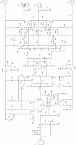
Amp with buffer: (symamp2.gif)
Inputvoltage: 0.3v
Outputvoltage: 13.5v into 4 ohms
2nd: 128uV
3rd: 121uV
Sorry, had to zip the gif, was too big...
BTW, this amount of distortion is not really bad, the difference
in thd was not really audible, only trebles got slightly better.
There are very good sounding amps with much higher distortions...
Have you replaced the mjl3281/1302 models in spice ? This is a must,
the original mods from onsemi are bad.
Look at the outputstagedistortionthread, there you can get corrected
models.
Mike
Mike,
your amp looks nice! I also tried some designs, which used followers between the input stage, and the VAS. I found that more current on the follower speed up the amplifier. Double emitter follower even better, to get higher poles.
Another modification I recommend, to use some zener regulators for this followers! It will reduce the dissipation, and the memory effects as well.
To avoid the oscillation use serially connected RC network parallel with R26, and R27. If You interesting in this solution, we can discuss the planning of the values of it!
sajti
hi thanh !
Hmm, with 700mv inputvoltage my amp is far above clipping...
Which outputvoltage does this input result ?
I choosed 300mv, as this is already "high" power, but not too near
to clipping. And typically ~14volt output is already 25watt rms for me,
(have 4ohm boxes) and that's already unacceptable volumelevel.
(For my neighbors at least) My speakers have ~90db/W...
Mike
sajti said:
Mike,
your amp looks nice! I also tried some designs, which used followers between the input stage, and the VAS. I found that more current on the follower speed up the amplifier. Double emitter follower even better, to get higher poles.
Another modification I recommend, to use some zener regulators for this followers! It will reduce the dissipation, and the memory effects as well.
To avoid the oscillation use serially connected RC network parallel with R26, and R27. If You interesting in this solution, we can discuss the planning of the values of it!
sajti
Hi sajti !
Yes, i am interested, do you have some schematics ? I am not fully
sure what you describe, does this mean exchanging q144/q145,
connecting the emitters via resistor ? (or better ccs to get voltagesupplyindependent)
But as the swings at these transistors are minimal (~3mv), shouldnt
this exclude memoryeffect ?
In fact, i want to get rid of the buffer in the actual config, it creates
some spikes in bandwidthrolloff.
Another thing, yesterday i included a voltagestabilizing to vas and
inputstage, getting rid of effects from PSU, it seems to work as the
sound got cleaner. But now i have the typical SS-amp weakness,
these annyoing "sss" from singersss are now much stronger than before...

More fascinating: I already got rid of this by replacing the inputbjts with jfets.
Do you have any idea ? Does this mean that even harmonics can
mask this effect ? Or is this just typical for BJTs ?
For comparison i will now build an ultrasimple asymetrical with
R-loaded vas. (8 bjts total) Just want to know if my amp is already
"overdesigned" or simply too slow... And i will check the mosfets
again, but not IRFs, i tend to try the sj201/sk1530.
I like the sound of my amp, it has really perfect bass, separation,
mids/dynamics/details, only these "sss" are keeping it from beeing
my final one. I wanted to avoid ClassA...
Mike
MikeB said:
Hi sajti !
Yes, i am interested, do you have some schematics ? I am not fully
sure what you describe, does this mean exchanging q144/q145,
connecting the emitters via resistor ? (or better ccs to get voltagesupplyindependent)
But as the swings at these transistors are minimal (~3mv), shouldnt
this exclude memoryeffect ?
In fact, i want to get rid of the buffer in the actual config, it creates
some spikes in bandwidthrolloff.
Another thing, yesterday i included a voltagestabilizing to vas and
inputstage, getting rid of effects from PSU, it seems to work as the
sound got cleaner. But now i have the typical SS-amp weakness,
these annyoing "sss" from singersss are now much stronger than before...
More fascinating: I already got rid of this by replacing the inputbjts with jfets.
Do you have any idea ? Does this mean that even harmonics can
mask this effect ? Or is this just typical for BJTs ?
For comparison i will now build an ultrasimple asymetrical with
R-loaded vas. (8 bjts total) Just want to know if my amp is already
"overdesigned" or simply too slow... And i will check the mosfets
again, but not IRFs, i tend to try the sj201/sk1530.
I like the sound of my amp, it has really perfect bass, separation,
mids/dynamics/details, only these "sss" are keeping it from beeing
my final one. I wanted to avoid ClassA...
Mike
I mean to increase the bias of the q144/145. The simplest way to decrease the emitter resistor value. If the voltage swing is just 3mV on this stage, than the memory effect is not too big.
I don't know waht cause the "sss" effect. Did You check the amp for oscillation? Is it stable with any kind of load? If Your open loop gain is 56000, and the closed loop is about 45, than You have 62dB nfb, without real compensation. It quite risky, and can result oscillation.
I read an article about this kind of sound. The writer think that this sound caused by the TIM. He wrote that too big feedback, and not properly planned phase response cause this effect....
sajti
Hi sajti !
For checking i just opened the loop, adjusted r27 (only little) to
give no dc-offset and then checked the ratio input<->output, with
load as shown. (Sim only)
I can check with different loads, but shouldn't differ much due to
tripledarlington.
I thought OL-gain of 56000 is very low ? I already had an amp with
1:1.500.000, didn't oscillate.
I already changed feedbackcaps to values giving proper response
to a squarewavesignal, this improved sound. I changed c4 to 33pF,
and added RC (1nF+150ohm) between r26/23 & r27/r24.
The amp does not show any sign of oscillation, at least none of
oscillations i can detect without scope.
The typical signs for oscillation i observe are:
- Does quiscentcurrent change in strange ways ? different LS-cables,
different speakers, changing volumepot, unsteady measuring...
- Any noticable sound when touching amp-output ?
- When measuring the current, does voltmeter already show numbers
when going near to the measuringpoints ?
- Does some tones sound noisy ?
Do you know more signs ?
Of course i can't detect local oscillations this way, but scopes are
really expensive !
About the "sss" sound, many complain about this problem, seems
that nearly all SS-amps show this... I'm just frustrated that mine
also does it now.
Remember this thread ?
http://www.diyaudio.com/forums/showthread.php?s=&threadid=21315
Mike
Mike,
I think that 56000 open loop gain is too high. I never used over 300-400. Too high nfb can results TIM. Unfortunately You can check the TIM only with scope
Unfortunately triple darlington not avoid the gain change caused by the load. This only transform up the load resistance for the VAS. Try it with sim! Apply some different load, and check it.
You can avoid this effect, ií You mount two resistors. So add two 100kohm resistors, one from the base of q16, and one from the base of q17 to the ground. This will add some fixed load for the VAS. Of course it will decrease the open loop gain, but increase the pole.
I would increase the emitter degeneration resistors in the input stage, and increase the VAS current up to 3-4mA.
But of course these are my solutions, and not necessary to use them.
sajti
Ooops, forgot to mention, i already had these 100k load to vas,
but the change to sound was subtile or none...
I also added a 100nF across R1, not much, but changed something
with the sound. Cap should be larger, but only had 100nF's, wanted
to avoid electrolytics.
Did you look at the thread ?
It doesn't help me, it gives 2 conclusions:
1, my amp is "too good", revealing any weakness from recordings
2, my amp is "too bad" to drive my tweeter correctly...
Somehow, i believe it's both of it ?
Mike
MikeB said:Ooops, forgot to mention, i already had these 100k load to vas,
but the change to sound was subtile or none...
I also added a 100nF across R1, not much, but changed something
with the sound. Cap should be larger, but only had 100nF's, wanted
to avoid electrolytics.
Did you look at the thread ?
It doesn't help me, it gives 2 conclusions:
1, my amp is "too good", revealing any weakness from recordings
2, my amp is "too bad" to drive my tweeter correctly...
Somehow, i believe it's both of it ?
Mike
I think it not so hard to reduce the open loop gain. I would never use nfb over 20dB. I will post simple schematic I planning now. This will be very simple assymetrical amplifier with low feedback and with not too much parts...
sajti
oops...
Damn it, forgot to listen the same CD on a different system...
I sssuddenly got thisss cold pfeeling hearing thisss, the "sss" still audible,
but trebles ? All distorted, no separation and so on...
And i thought the "hifi"-system here @ work is good...
(Harmon Kardon AVR4000 + Teufel Speakers)
Okay, never use "Queen greatest Hits II" for listeningtests !
(I should have known better, samplers are always bad)
Unless you want to test the "sss"...
Mike
Hi, Mike,
Got another suggestion. Put Cap-multiplier for the +/- rail for all the stages before the final transistor. I experimented this and it makes quite a difference in sound.
Also, why dont we insert something about "Minimum Component" philosophy? A phylosophy that the best sound comes from minimum stages where the audio signal should pass. We can design for "UltraHifi" very low distortion amp, but usually ends up in complex cct. Simpler cct/stages maybe not so "super" in measurement, but sometimes it sounds better. So only put the essential stages (but with very good design for each).
You wanted to eliminate Q144/145? Looks like you are going into this track.
Hi lumanauw !
Yes, because of this "minimum component" philosophy i wanted to
try the ultrasimple asymamp (8bjts total). I wanted to compare the
sound of a that fast circuit with my now built.
But maybe i can't get rid of this "problem" with trebles unless i change
to tube-topology ?
My experience today, listening to another hifi after a while, was a bit
shocking for me, i found the sound disgusting in compare to mine.
I believe that for getting this "ultrahifisuperlowdistortive" circuit,
you need too many compromises and end up with a not good sounding
amp, but measuring superb for a 1khz sinewave.
Playing in sims showed, that the less parts, the better & faster transient
behaviour i get. That's why i want to get rid of the q144/145.
At least it's much easier for simple circuits to get proper feedback.
(Or you use separate feedbackloops for each stage)
Hey, some idea, maybe start a challenge, who can build the amp
with the least components (good sounding of course) ?
But will be difficult to beat JLH... (4bjts)
I am not familiar with Cap-multiplier, can you explain ?
Mike
Mike,
I believe that I can get better performance with less parts. But not so easy to decide yourself to use or not use one part. The simplest amp can contains only one transistor. Why not use it?
If You go to the way, use by Hugh for Aksa amplifiers You can use only 8 transistors. But if You redesign the output stage to triple darlington, You get better sound? Or worse? If You avoid the bootstrapping capacitor, and add ccs, You increase the number of the transistors. Is it better, or worse???
This questions are the most interesting....
sajti
Hi sajti !
Yes, that was the idea. I wanted to start with this 8bjts-style, as used
for the aksa. Then add parts and check what the sound does with each
"improvement". I would start with the bootstrapped vas, then
replace it by a ccs. Also i want to check what the cfp-input really does
to the sound. And i want to check what the currentmirror does.
I will use the same bjts for output, the mje15030/31 and mjl1302/3281.
And also i would check for the "benefits" of a tripledarlington.
But i will revert the whole circuit in comparison to the aksa, to enable
the use of nchannel-jfets in input. (need to know if they really sound
different, or if the difference was only audible because these jfets were
slower than the bjts)
Mike
Hmm, some improvements only took a few seconds to decide...
Optimizing feedbackcaps for example was immediately audible, it was
like ...WOW!...
Also, when i first time powered up the symamp, the improvement in
bass was the first thing i noticed. (compared to all previous amps)
You are speaking of subtile changes ? Or listen to it with as many
recordings as possible ?
Mike
Both of them. Many times You can hear the change. But You need time to decide that the change is positive or negative. As You inrease the quality, every step will results smaller change in sound quality. And there will be some change, which will be no better or worse, just different. And not easy to decide that You will keep it, or fall back...
sajti
sajti
Hi, Mike,
This is the cap multiplier. Q14 and Q15. It multiplies the cap by HFE value, because the only thing that is attached to the base is cap and small current leakage from R for turning the Q on. It gives very clean +/-rail for front ends. The R and C makes a lowpass filtered that is injected to base.
Mike, I really looking forward your "invesgation report" on 8 Transistor design transformed to your design. Step by step. What every single change makes on the sound. Like R vs CCS, current mirror (not every body likes it), single / triple darlington output etc. Maybe the format is something like peufeu website reported?
Scopes are not that expensive. You can go to local electronic market, usually there are used ones for fair price. Low MHZ are OK, not need high-end scopes for audio (except you want to examine RF modulation on audio tracks )
This is the cap multiplier. Q14 and Q15. It multiplies the cap by HFE value, because the only thing that is attached to the base is cap and small current leakage from R for turning the Q on. It gives very clean +/-rail for front ends. The R and C makes a lowpass filtered that is injected to base.
Mike, I really looking forward your "invesgation report" on 8 Transistor design transformed to your design. Step by step. What every single change makes on the sound. Like R vs CCS, current mirror (not every body likes it), single / triple darlington output etc. Maybe the format is something like peufeu website reported?
Scopes are not that expensive. You can go to local electronic market, usually there are used ones for fair price. Low MHZ are OK, not need high-end scopes for audio (except you want to examine RF modulation on audio tracks
)Attachments
- Status
- This old topic is closed. If you want to reopen this topic, contact a moderator using the "Report Post" button.
- Home
- Amplifiers
- Solid State
- Have you ever succeed in buiding a input stage with current mirror?