Back to your previous post about different sound, you may play with trimpot settings, to set different plate voltages and listen to results and compare them. It's an interesting game! ")
If you have a functional generator and an oscilloscope the game may be more interesting: run triangles on input and see how they change on output depending on settings. Then compare character of distortions you've seen on the scope to what you've heard listening to the music with such voltage settings.
Speaking of best sounding devices... I would suspect transistors with less variations of beta on collector-emitter voltage to sound better.
Yes, I've been doing that , though just by ear. You're right, it IS interesting. I had read many posts from way back about where the best place to run the 417A was . It looks like one or two guys posted their opinions and then everybody else just followed. I've been trying these at less than half recommended current and Vp all the way up to 1.5 the recommended values. There's way more usable space there. They've been sounding very good at lower Pa.Wavebourn said:Back to your previous post about different sound, you may play with trimpot settings, to set different plate voltages and listen to results and compare them. It's an interesting game!
If you have a functional generator and an oscilloscope the game may be more interesting: run triangles on input and see how they change on output depending on settings. Then compare character of distortions you've seen on the scope to what you've heard listening to the music with such voltage settings. [/B]
I have a small kit built one that does square and sine but it has been acting glitchy lately and I haven't used it much. Maybe it's time for a better one - with Triangles!!
Speaking of best sounding devices... I would suspect transistors with less variations of beta on collector-emitter voltage to sound better. [/B]
Well, I'm willing to try, but I haven't found anything that has the voltage rating that has that kind of info on the data sheet. (Well, I did find the MJL4302A, a high power audio transistor , and also 2SA1862) Do you know any that would work?
I'm listening to this thing right now and Man(!) does it ever sound good!. If I can get the time I'll probably build another pair for the Low Freq. (<800Hz.) amps this weekend.
Thanks Wavebourn!
Hi Wavebourn
Still hunting for a function generator to do the tests you recommended so in the meantime I went ahead and put in the first new output transistors ( MJL4302A ) . They're obviously different. The sound makes me think that at at 600pF the Cob is probably much higher than the MJE5731A's but there is no figure given on the -5731A data sheet so I can't say for sure. One thing is for certain though. This is a great sounding circuit !!!
I have to thank you again. It has opened my ears to the possibility that I'd become used to a sound rooted in CCS circuitry which I was always trying to cure by fixing other things. It's fantastic!
Hearinspace said:Hi Wavebourn
Still hunting for a function generator to do the tests you recommended so in the meantime I went ahead and put in the first new output transistors ( MJL4302A ) . They're obviously different. The sound makes me think that at at 600pF the Cob is probably much higher than the MJE5731A's but there is no figure given on the -5731A data sheet so I can't say for sure. One thing is for certain though. This is a great sounding circuit !!!
I have to thank you again. It has opened my ears to the possibility that I'd become used to a sound rooted in CCS circuitry which I was always trying to cure by fixing other things. It's fantastic!
Thanks for posting your results!
If you like the direction you're going, you're on a good track.
I've been getting great results with MOSFETs, in a direct coupled power tube driver circuit as I showed earlier.
I would like to see the circuit you're using and what it's driving. Is it a driver for an output stage or a line amp or what? I don't recall the context.
Now you have me very curious to compare the sound of constant voltage with constant current anode loads. I will probably build a parafeed stage for this.
Cheers,
Michael
Michael Koster said:
Thanks for posting your results!
If you like the direction you're going, you're on a good track.
I've been getting great results with MOSFETs, in a direct coupled power tube driver circuit as I showed earlier.
I would like to see the circuit you're using and what it's driving. Is it a driver for an output stage or a line amp or what? I don't recall the context.
Now you have me very curious to compare the sound of constant voltage with constant current anode loads. I will probably build a parafeed stage for this.
Cheers,
Michael
Hi Michael,
Sure! First though I have to start by saying that I'm just happy as a clam to have found this place. Watching people snipe and argue over matters of personal taste on other forums I was beginning to despair . . . . . It's so neat to be in the company of people who just want to share knowledge about the good stuff (as Wavebourn put's it "I just live here, breath this beautiful electronic air... And wish to everyone to enjoy it for free" . . . Sweet!
 )
)I'll try scanning a sketch later but for now -
Amp in question is breadboard power amp for 800Hz and up horn in a biamped set-up. It goes like this :
Input RCA > Grid Choke >417A/5842 (Right now Vp is at 125VDC with Rk 75 Ohm, Ck 1360uF, Plate Load is this ) > Coupling cap 0.01uF > VT-25 output tube (Vp today is set at roughly 350VDC with Rk 2.5K 5 Watt pot , Ck 600uF, Plate Load is a Cascoded Mosfet CCS using DN2540N5 and IXTP01N100D set at about 28 mA ) > 10K Parafeed output transformer with 3.3uF parafeed Cap. The VT-25 filament is heated with a simple LC filter into LT108- CCS circuit. The B+ is 488 VDC.
Wavebourn also said he might show a way of doing his circuit for a direct coupled circuit (which I'd really like to try). I think I 've got just enough B+ as is to pull out the output tube's CCS and use a plate choke . Probably also a good idea to try his circuit on the output tube in the cap coupled version .
Thanks Michael.
Hi Hearinspace;
now you may try to load your VT-25 on simpler SVCS to explore different load regimes and impact of them on sound (I'll draw you a sketch later -- you can convert your cascoded CCS into it).
As you can see from your experience of playing with tube regimes, the reality is a bit different from beliefs and theories peoples on forums often argue about.
Wavebourn said:Hi Hearinspace; now you may try to load your VT-25 on simpler SVCS to explore different load regimes and impact of them on sound (I'll draw you a sketch later -- you can convert your cascoded CCS into it).
Forget it!
 The SVCS on the driver stays!! When you're ready I'll build a new board for the VT-25
 As you can see from your experience of playing with tube regimes, the reality is a bit different from beliefs and theories peoples on forums often argue about.
Yep! Experience rules!! Thanks for your help Wavebourn, I'm really enjoying this!
Hearinspace said:
Hi Michael,
Sure! First though I have to start by saying that I'm just happy as a clam to have found this place. Watching people snipe and argue over matters of personal taste on other forums I was beginning to despair . . . . . It's so neat to be in the company of people who just want to share knowledge about the good stuff (as Wavebourn put's it "I just live here, breath this beautiful electronic air... And wish to everyone to enjoy it for free" . . . Sweet!
I'll try scanning a sketch later but for now -
Amp in question is breadboard power amp for 800Hz and up horn in a biamped set-up. It goes like this :
Input RCA > Grid Choke >417A/5842 (Right now Vp is at 125VDC with Rk 75 Ohm, Ck 1360uF, Plate Load is this ) > Coupling cap 0.01uF > VT-25 output tube (Vp today is set at roughly 350VDC with Rk 2.5K 5 Watt pot , Ck 600uF, Plate Load is a Cascoded Mosfet CCS using DN2540N5 and IXTP01N100D set at about 28 mA ) > 10K Parafeed output transformer with 3.3uF parafeed Cap. The VT-25 filament is heated with a simple LC filter into LT108- CCS circuit. The B+ is 488 VDC.
Wavebourn also said he might show a way of doing his circuit for a direct coupled circuit (which I'd really like to try). I think I 've got just enough B+ as is to pull out the output tube's CCS and use a plate choke . Probably also a good idea to try his circuit on the output tube in the cap coupled version .
Thanks Michael.
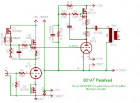
Well I guess great minds think alike. Here's what I'm wiring up on the breadboard. The MOSFET (actually a sort of IGBT) on the output is a so-called anti-triode which shares the load 50/50 with the 801A. The 801A sees 2X the Zpri of the OPT, in this case it sees 16K. If I can get close to 1000V P-P swing on the anode I should get about 15 watts Po. I will need to drive the grid to +30 to do this, using the A2 drive circuit recycled from the 4-65A experiments.
I thought a good use of the anti-triode would be to help lower the circuit impedance of a high impedance triode like the 801A, which I believe is similar to your VT-25. Actually I think mine are VT-62s.
Maybe I can modify this to try a constant-current version of the output instead of the (now) constant voltage. It would be interesting to compare notes. I'm running the 417A at ~170V/12mA
Cheers!
Michael
Attachments
Great minds eh? Well, it feels good to be treated like an equal but if I pretend I deserve it now I'll just look even more stupider later. I don't quite get the schematic so am going to redraw it tonight to see if I can understand what's happening with all the voltages.
Processing . . . . . . . . .
Processing . . . . . . . . .
Michael Koster said:. . . . I'm running the 417A at ~170V/12mA
Hi Michael, Do you in fact have three power supplies?
Wavebourn, The boards are in on the bass amp drivers. Hard to say yet as it needs a few hours (Well the first ones did anyway) but I gotta tell ya! They're great!
Only minus is gain. down a little bit though not much. I'll twiddle the pots for a few days to see where they sound best by ear. Still looking for the right test stuff . . . .
Only minus is gain. down a little bit though not much. I'll twiddle the pots for a few days to see where they sound best by ear. Still looking for the right test stuff . . . .
Thanks. I was thinking about LED, but in this case some FET based breakdown diode may be used.Hearinspace said:Yes the cathode resistors are shunted with capacitors. Right now voltage measures 1.1 - 1.2 VDC across the 75 Ohm cathode resistors with a Vp = approx. 125VDC.
Wavebourn said:. . . . .but in this case some FET based breakdown diode may be used.
Do you mean instead of the cathode resistor? I haven't used a FET like that before - Is there an advantage over using the resistor?
Still listening at 12:45, it sounds good!
Thanks
Hearinspace said:Hi Michael, Do you in fact have three power supplies?
It's a clever design, but it needs three supplies so that it can be direct coupled throughout. The 1100 and 60V supplies are stacked on the 210V supply.
Sheldon
Sheldon said:
It's a clever design, but it needs three supplies so that it can be direct coupled throughout. The 1100 and 60V supplies are stacked on the 210V supply.
Sheldon
OK, to clarify, the 210 and 1100 are stacked for direct coupling. The third supply (60V) is needed to drive the grid positive for class A2 and could be derived from any source e.g. screen grid supply if you had a pentode... BUT arranging it this way provides a direct return path to the cathode, therefore grid current does not have to be dealt with in the current loop of the driver anode or the power tube cathode. The 60V supply in my breadboard amp (common to both channels) consists of a toroid, a bridge rectifier, and a capacitor ;-) Also of note is the 210 and 60 supplies can be shared in a stereo amp because there are no common return current paths to induce crosstalk. Eventually the MOSFETs should probably be cascode for better PSRR but it's very good as it is.
Cheers,
Michael
PS if you trust the isolation of the MOSFET active loads on the outputs, then all the power supplies and filters can be shared in a multichannel amplifier
Hearinspace said:
Do you mean instead of the cathode resistor? I haven't used a FET like that before - Is there an advantage over using the resistor?
I mean, what is called low voltage Zeners are usually FET based devices. An infrared LED can be probably used, but it wants about 1.5V, more than your cathode resistor provides.
The advantage is, low dynamic resistance without usage of capacitors.
- Status
- This old topic is closed. If you want to reopen this topic, contact a moderator using the "Report Post" button.
- Home
- Amplifiers
- Tubes / Valves
- Gyrator Question