Michael Koster said:
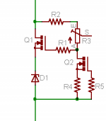
I wonder if something like this would work?
Both will work, if there are no Zener available capable of required dissipation.
posted by Wavebourn
They have cut-off voltages below 4V. Try 27V Zener with 100 Ohm resistor in series.
posted by Michael Koster
I wonder if something like this would work?
posted by Wavebourn
Both will work, if there are no Zener available capable of required dissipation.
OK, I'll try both ways. Can you tell me what the resistor and zener on the MOSFET and PNP are doing? I'd like to understand their functions so I can work out the needed values myself. (I still haven't read the chapter on MOSFETS yet.)
Thanks you guys!!!
Resistor provides current through Zener so it is in ranges between minimal current (when it's dynamic resistance is too high) and max current (when it is too hot). You should remember that MOSFET will need something from 3.5 to 4V between gate and source to start working, so the resistor value should be calculated for about 4V of a voltage drop on the desired current through Zener.
You can see curves for typical Zeners and for typical IR MOSFETs for yourself. I don't think it is good to copy them from datasheets and post here due to copyrights.
For BJT version drawn by Michael you will need a similar resistor between base and emitter, but for other purposes as well: to compensate a sum of "dirty current" that is specified usually as Vcbo for BJT, and leakage current for Zener. Also, consider that current through Zener will be Beta times less than collector current that will supply the current to cathode of your tube, so the resistor between base and emitter also will serve the function to increase this current to the desired value (as I mentioned for the case of MOSFET). Consider voltage drop between base and emitter around 0.65V
But I believe that 27V Zener like 1N5361B with 100 Ohm resistor in series will serve fine. 100 Ohm is 20 times higher than dynamic resistance of this Zener that is 5 Ohm, so variations of it's dynamic resistance with current will impact 20 times less than with no resistor. Also, you will use this resistor to measure voltage drop across it, to set 2.8V for 28 mA idle current for your tube.
Hearinspace said:OK , I think I've got it. Just to confirm - With both BJT and MOSFET the circuit needs to have a zener with nominal voltage = desired cathode voltage minus turn on V of the BJT or MOSFET?
Right.
Advantages of transistors are: higher current is available if to mount them on heatsink, also dynamic resistance is lower than zener's dynamic resistance, but it is more frequency dependent since transistors have limited Ft, plus input capacitances. MOSFET will probably need a gate stopper.
Hearinspace said:So for experimenting to find the best sounding operating point you could replace the zener with a trim pot and use to try different bias voltages?
I would rather switch Zeners in a string. However, a trimpot and MOSFET may be a good idea, since some low voltage mosfets have big enough forward transconductance. For example for 27V you have a resistor between source and gate with 3.5V drop, and a trimpot between drain and gate with 23.5V drop.
Opening a datasheet for (for example) MTP50N06V.
http://www.datasheetcatalog.org/datasheet/motorola/MTP50N06.pdf
It is hard to tell from figure 2 for 30 mA only, but let it be 1 Amper/Volt only (about 1t Amper/Volt at 20A current as you can see from the graph).
That means dynamic resistance will be 27/(3.5*1) = about 35 Ohm.
Good for experiments, but I'm afraid too temperature dependent for production.
Wow, you were up early!
I'm sorry but I don't know what 1t Amper/Volt means. And I think 27/(3.5*1) = about 35 Ohm might be a typo. I get 7.71. I'll get some zeners and a trimmer and try both anyway.
The other thing I'd like to ask about is the direct coupled circuit. It seems to me that what everybody wants in a Direct Coupled circuit is to get rid of the coupling cap (or interstage transformer) With the driver plate voltage control that can be had with the SVCS what is the advantage of using the biased capacitor coupling?
Thanks Wavebourn . I'm having a lot of fun with this!
Wavebourn said:
I would rather switch Zeners in a string. However, a trimpot and MOSFET may be a good idea, since some low voltage mosfets have big enough forward transconductance. For example for 27V you have a resistor between source and gate with 3.5V drop, and a trimpot between drain and gate with 23.5V drop.
Opening a datasheet for (for example) MTP50N06V.
http://www.datasheetcatalog.org/datasheet/motorola/MTP50N06.pdf
It is hard to tell from figure 2 for 30 mA only, but let it be 1 Amper/Volt only (about 1t Amper/Volt at 20A current as you can see from the graph).
That means dynamic resistance will be 27/(3.5*1) = about 35 Ohm.
Good for experiments, but I'm afraid too temperature dependent for production.
If you want to use a few more parts, I think you could keep the impedance low by referencing voltage drop across a resistance at constant current. You could then use a 1A, 600V MOSFET that has a gfs of only 0.1 A/V and still be about 10 ohms (1/gfs) dynamic resistance. One might try a LND150 for Q2 and possibly do away with the resistors and D1. I don't know about temperature stability of this approach, though. It would depend on the Q2 CCS current stability
Attachments
Michael, 'Just put the 2N700 on the 417A . Nifty!
With the MOSFETS running at 2.48 (the other at 2.55) Volts the tube is only getting 1 mA Ip (@ Vp 130VDC - I had to run it up to 202VDC to get 10mA out of the tube) but it doesn't seem to matter , at 1mA it sounds great. I'm surprised it can do anything at all at such low plate current let alone sound good. Thanks for motivating me to try this.
With the MOSFETS running at 2.48 (the other at 2.55) Volts the tube is only getting 1 mA Ip (@ Vp 130VDC - I had to run it up to 202VDC to get 10mA out of the tube) but it doesn't seem to matter , at 1mA it sounds great. I'm surprised it can do anything at all at such low plate current let alone sound good. Thanks for motivating me to try this.
Hearinspace said:I'm surprised it can do anything at all at such low plate current let alone sound good.
From here: http://coupling-triode.blogspot.com/
""If one compares today's circuits with older ones one will see that today triodes are driven with a substantially higher current than in former times. One tries to get on a straight part of the graph to get low mutal conductance slope destortions. Remaining slope distortions are minimized with negative feedback. This makes special demands which from a typical low frequency triode like the ECC83 are only partially fulfilled however better by RF valves. These (e.g. ECC85) are often seen in sound amplifiers now.
We do not have to use triodes this way. Mutal conductance slope distortions are not an issue if anode current is held constant. One way to achieve this is to operate the triode with no-load and thus to work µ-gain. To get this operating condition the triodes internal resistance should be much smaller than the external load resistor. This operating condition can be reached easily using triodes with low µ like the ECC82 µ=17 but for high µ triodes like the ECC83 µ=100 we must think about a solution.
It would be possible to achieve this for high µ triodes by puting several in parallel without changing the voltage ratio. In this way the gain will increase to µ and the mutal conductance slope distortions will tend to zero. Alternatively it is possible to increase the external load and to reduce the current at the same time. By this means the voltage ratios are maintained.
The table on S.144 in the Valvo manual 1962-63 for ECC83 illustrates this:
Operating voltage 250V, output voltage 6V RMS, AC load = 3xRa
Ra=47K Ia=1,95mA voltage gain amount =36 distortion K=5.6%
Ra=100K Ia=1,23mA voltage gain amount =48 distortion K=5.1%
Ra=220K Ia=0,67mA voltage gain amount =57 distortion K=4.4% ""
Your load is very low with gyrator, so you can run at low currents without much distortion.
Sheldon
Hearinspace said:Michael, 'Just put the 2N700 on the 417A . Nifty!
With the MOSFETS running at 2.48 (the other at 2.55) Volts the tube is only getting 1 mA Ip (@ Vp 130VDC - I had to run it up to 202VDC to get 10mA out of the tube) but it doesn't seem to matter , at 1mA it sounds great. I'm surprised it can do anything at all at such low plate current let alone sound good. Thanks for motivating me to try this.
Interesting. I have these mil-raytheon 5842 that are all over the map
but 200V for 10mA at -2.5Vg is outside what I've seen in NOS so far!
I have one that wants 190V... I swap it into the side that wants more
grid bias on the output tube to keep the driver currents more or less
balanced side to side, be it stereo SE or PP. The new JJ tubes are nice
for consistency but they don't make a 417A type which would be hard
to make consistent. Best to buy more and match them up.
Sheldon and Darus agree with your and my own observations, it's
not so much "high current == linear", but rather but how flat the load
line for minimizing distortion and good sound.
The source of THD is as stated the variation of rp with signal current swing. If rp is small compared to the load than you get reduced distortion.
HOWEVER
It is my contention that reason for running at higher currents is not so much to get rp lower but to better charge/discharge the Miller Capacitance of the following stage (VT25 in this case). You need current capability to avoid slewrate limiting. Slewrate limiting will introduce Transient Intermodulation Distortions (TIM).
Cheers,
Ian
gingertube said:The source of THD is as stated the variation of rp with signal current swing. If rp is small compared to the load than you get reduced distortion.
HOWEVER
It is my contention that reason for running at higher currents is not so much to get rp lower but to better charge/discharge the Miller Capacitance of the following stage (VT25 in this case). You need current capability to avoid slewrate limiting. Slewrate limiting will introduce Transient Intermodulation Distortions (TIM).
Cheers,
Ian
That's a good point. A gyrator load is probably among the lowest
capacitance loads but still finite. A MOSFET would be Crss through the
gate for the most part, with Ciss and Coss bootstrapped. FQP1N60
is 4pF Crss
The 801A has 6pf Cg-p and in-circuit gain af about 6 (=36pf Cmiller)
+ 4.5pF Cg-k
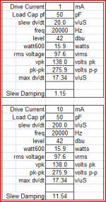
If I run 1mA and 50pf through my slew calculator I get 20V/uS or
about 100V max rms 20KHz sine wave. I would feel more comfortable
with a little more "slew damping" factor i.e. excess drive current. I
would probably design the driver here for about 100-200V/uS which
would probably require 10 or 12mA idle current.
Cheers,
Michael
Attachments
I should mention that the drivers I changed were in the LF amp using a px25 not vt-25. The HF and LF amps were built for very different loads so to keep continuity in sound the drivers for both are 417A/5842. I wanted to try Michael's solution but time was limited and the driver circuit in the bass amp was easier to get at.
Anyway, I think I might have been less surprised if the 1mA wasn't driving the output tube through a coupling cap . . . . . in the bass amp! . . . . . running at approx. 1/15 the previous Ip ! and the sound actually has more snap !!
. . . . . though after a few hours' listening something is starting to bug me a little. I think I need to get some decent test gear.
gingertube said:The source of THD is as stated the variation of rp with signal current swing. If rp is small compared to the load than you get reduced distortion.
HOWEVER
It is my contention that reason for running at higher currents is not so much to get rp lower but to better charge/discharge the Miller Capacitance of the following stage (VT25 in this case). You need current capability to avoid slewrate limiting. Slewrate limiting will introduce Transient Intermodulation Distortions (TIM).
I've had the impression that TIM results from slewrate limiting in circuits with high feedback. At least, that's the only context where I've seen it discussed - given my limited exposure. At any rate, there is little musical content above 10kHz. Certainly the energy above that range is much lower than it is below 10k, which should provide more margin than a calculation at max swing suggests.
Sheldon
TIM again...
I've been following the TIM debate since the late 1970s when I met
an engineer from Sansui named Susumu Takahashi, who was an
inventor of their 200V/uS "Diamond" driver circuit(1).
I'm going from memory here but I believe that circuits which depend on
high HFB for linearity have need for internal slew rates which are a
larger multiple of the signal slew rate(3)(4), than would be the case with
less NFB, to avoid TIM distortion. I believe TIM distortion can be induced
without negative feedback (2)(3).
References (2 and 4 are AES (sorry...) but #3 has the meat of it):
(1) "Differential Amplifiers"
Takahashi, et. al. 1978
http://www.patentgenius.com/patent/4229705.html
(2) "Method for Measuring Transient Intermodulation Distortion (TIM)"
Leinonen, Oala, Curl 1976
http://www.aes.org/e-lib/browse.cfm?elib=2229
(3) "An Overviev Of SID and TIM"
Jung, Dtephens, Todd 1979
http://waltjung.org/PDFs/SID_TIM_1.pdf
(4) "Transient Intermodulation Distortion in Commercial Audio Amplifiers"
Otala, Ensomaa 1974
http://www.aes.org/tmpFiles/elib/20090703/2763.pdf
Michael Koster said:If I run 1mA and 50pf through my slew calculator I get 20V/uS or
about 100V max rms 20KHz sine wave. I would feel more comfortable
with a little more "slew damping" factor i.e. excess drive current. I
would probably design the driver here for about 100-200V/uS which
would probably require 10 or 12mA idle current.
Where do we start to see TIM that's audible? Sure, more current would eliminate the issue completely, but there are always trade offs. I don't know what the schematic is, but I think I can safely assume that it's class A1. In that case we are probably looking at a swing of 30V or so. So let's say about 20-25Vrms. That's 1/4-1/5 of of the figure for the slew limit of 1mA. I can't imagine that we have much music content at 20kHz that approaches the maximum swing. Maybe clicks and pops from records, but those are intermittent noise, and disrupt the sound anyway. So as a practical matter, would we expect to measure, or hear, TIM in this particular situation?
Sheldon
Sheldon said:
Where do we start to see TIM that's audible? Sure, more current would eliminate the issue completely, but there are always trade offs. I don't know what the schematic is, but I think I can safely assume that it's class A1. In that case we are probably looking at a swing of 30V or so. So let's say about 20-25Vrms. That's 1/4-1/5 of of the figure for the slew limit of 1mA. I can't imagine that we have much music content at 20kHz that approaches the maximum swing. Maybe clicks and pops from records, but those are intermittent noise, and disrupt the sound anyway. So as a practical matter, would we expect to measure, or hear, TIM in this particular situation?
Sheldon
If the voltage swing is only 25Vrms instead of 100Vrms, the current
needed will be proportinately lower. My last breadboard was class A2
and used 100Vrms grid drive. I used 10mA on the 417A. So I guess I
was giving you my context. The VT-25 output stage in class A1 will
probably be around 20-30Vrms as you suggest.
Something to keep in mind, in the slew calculator example above
we're asking the tube to actually deliver 1mA of signal current at
20V/uS. If it's going to do this in a linear way with small phase shift
etc. then 1mA should be a relatively small impact on the load line,
implying relatively low Ri tube and op point, and relatively larger
standing current vs. signal current. That's the point in having a
"slew damping factor" which is the ratio of deliverable to required
current for a particular maximum slew rate.
As far as audibility of TIM and what kind of musical events are likely
instigators, one of the AES papers suggests cymbal crashes, tympani,
etc.. From my own recording experience I agree, and would add bells
as having high dv/dt capabability. > 2V/uS at line level is not uncommon.
Multiplying that to drive levels I think gives a reasonable target.
Michael
PS I saw slew limiting in the output transformer signal in the A2 amp
> 20 KHz at about 2X the design power of the OPT into a resistive
load. This is probably not a problem, but I think it's something to
watch out for with high impedance output tubes.
Michael Koster said:PS I saw slew limiting in the output transformer signal in the A2 amp
> 20 KHz at about 2X the design power of the OPT into a resistive
load. This is probably not a problem, but I think it's something to
watch out for with high impedance output tubes.
What does this look like? I made some transformers that gave nice HF performance in my 801 Loftin White amp, but were limited in the LF region. I was using it in a multi amp system at the time, so designed the transformer for that. But I wanted to use it as a headphone amp and possible other full range duty, so I ordered some nice transformers at considerable cost. I was surprised that I got obvious waveform distortion at full power starting somewhere above 10kHz. If I backed off the power the distortion went away. I assume this is sort of effect would be slew limiting by the transformer? I was disappointed to see this, but I can't say I actually hear it. But then I don't hear over 10K anyway.
Hmm, what limits the slew rate for the transformer. Inter winding capacitance? I don't normally see this effect, just the usual roll off at the upper limit.
Sheldon
- Status
- This old topic is closed. If you want to reopen this topic, contact a moderator using the "Report Post" button.
- Home
- Amplifiers
- Tubes / Valves
- Gyrator Question