Re: Re: HPS 3.0
I'm a PSpice user and I found the PSpice results (for noise) somehow pessimistic. The input stage simulates (with perfectly matched JFETs for an Idss of about 11mA) at 0.36nV/rtHz. Compare to 0.25nV/rtHz I was able to measure. But then the JFET intrinsic model is very poor, so no wonder there are significant differences...
Sigurd Ruschkow said:You mentioned simulations. I have found sims to be accurate regarding noise analysis.
If you simulate your design with your JFET models, how much discrepancy do you get between real world measurements and simulations?
And how does your JFET models look like graphically noisewise?
I'm a PSpice user and I found the PSpice results (for noise) somehow pessimistic. The input stage simulates (with perfectly matched JFETs for an Idss of about 11mA) at 0.36nV/rtHz. Compare to 0.25nV/rtHz I was able to measure. But then the JFET intrinsic model is very poor, so no wonder there are significant differences...
PMA said:Have you considered opamp + UG buffer to drive low imp FB network? I tried and it helps, a right way IMO.
I can very much support this view. No matter what the datasheets say opamps are not great sounding into such low impedances. A BUF634 will decrease transparency a bit but help tremendously to drive the riaa especially at high frequencies. What load does the poor 4031 work into at 20kHz?
analog_sa said:
I can very much support this view.
Thanks.
I learnt it from Walt Jung's RIAA pre.
Re: Re: Re: HPS 3.0
I simulated your input stage in Microcap and got 0.375nV/SQRT(Hz) @ 1kHz, and a total input noise of 45nV 20-20k.
The diff between 0.25 and 0.36 is not that bad when using off-the-shelf JFET models.
MY JFET models do not have the exact noise values you use from the selecting you did.
Sigurd
I simulated your input stage in Microcap and got 0.375nV/SQRT(Hz) @ 1kHz, and a total input noise of 45nV 20-20k.
The diff between 0.25 and 0.36 is not that bad when using off-the-shelf JFET models.
MY JFET models do not have the exact noise values you use from the selecting you did.
Sigurd
syn08 said:
I'm a PSpice user and I found the PSpice results (for noise) somehow pessimistic. The input stage simulates (with perfectly matched JFETs for an Idss of about 11mA) at 0.36nV/rtHz. Compare to 0.25nV/rtHz I was able to measure. But then the JFET intrinsic model is very poor, so no wonder there are significant differences...
analog_sa said:I can very much support this view. No matter what the datasheets say opamps are not great sounding into such low impedances. A BUF634 will decrease transparency a bit but help tremendously to drive the riaa especially at high frequencies. What load does the poor 4031 work into at 20kHz?
Look at the input stage stability with using a BUF634 in the loop. Not good

The input stage gain at 20KHz is about 20dB, the overall gain is 44dB. Therefore, the maximum output swing of the input stage (before the output stage is going into clipping at +/-22V) is about 1.4Vpeak which is about 20mA peak. Not a problem for THS4031 or AD795 (both supporting 100mA) or many other low noise high output current opamps.
About the sound of opamps, I strongly disagree with you, but I suspect you already know that. No further comments.
analog_sa said:And btw, why 3 stages?
Distributed RIAA network plus variable gain (the 48.7 ohm resistor in the second stage is in fact switchable). Can be probably done in two stages if you give up the +/-0.1dB precision, or if you tighten the passive components tolerances. To me, not worth another opamp.
syn08 said:
Therefore, the maximum output swing of the input stage (before the output stage is going into clipping at +/-22V) is about 1.4Vpeak which is about 20mA peak. Not a problem for THS4031 or AD795 (both supporting 100mA) or many other low noise high output current opamps.
Class B with opamp output stage biased at some 500uA - nothing to call home about.
Keep class A, you need at least 10mA bias current then - buffer.
PMA said:
Class B with opamp output stage biased at some 500uA - nothing to call home about.
Keep class A, you need at least 10mA bias current then - buffer.
I disagree. The same ol' same bitching about opamps output stage bias. I could easily point you at the 120dB open loop gain, you are going to moan about "open loop gain is bad" and "low frequency rolloff" and that in the context I couldn't care less about the MC preamp linearity at 22V output.
syn08 said:
About the sound of opamps, I strongly disagree with you, but I suspect you already know that.
True. I quite like the input stage and will probably try it out. Thanks for publishing. As i don't know how to adjust the compensation with a buffer and am too lazy to simulate i'll simply raise the feedback resistors by an order of magnitude. Surface noise will swamp this anyway.
And that second stage is a goner
Hps 3.1
HPS 3.1 is finished.
Here's the board level schematic (one channel only).
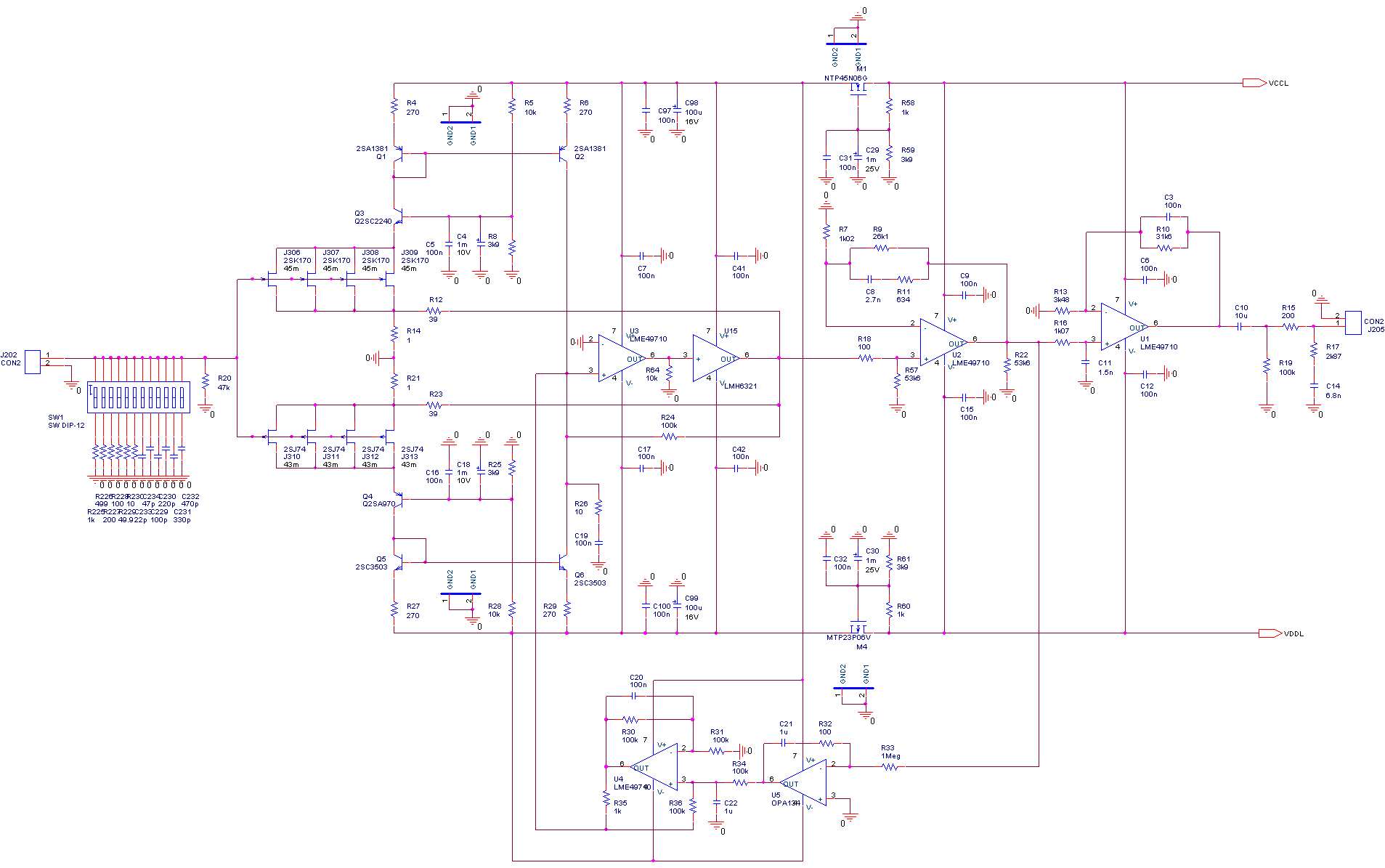
Changes since HPS 3.0:
- High power buffer added to the head amp. LMH6321 has 300mA output current, allowing the head amp to swing to +/-10V.
- LME49871 opamps, supporting +/-22V power supply voltage. This and the previous are now allowing an overall headroom of over 36dB.
- MC input only, fixed gain.
- Local serial regulators for the head amp.
- Current servo allows no caps in the signal path (except for the optional output cap).
- Servo also allows largely unmatched JFETs; Idss can be +/-3mA, so BL class devices need not to be matched.
- Extended input impedance range (10ohm-47K and 0pF to almost 1nF).
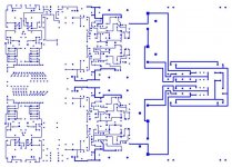
Dual mono construction, power supply schematic will follow soon.
Some measured noise performance in the next messages.
HPS 3.1 is finished.
Here's the board level schematic (one channel only).
Changes since HPS 3.0:
- High power buffer added to the head amp. LMH6321 has 300mA output current, allowing the head amp to swing to +/-10V.
- LME49871 opamps, supporting +/-22V power supply voltage. This and the previous are now allowing an overall headroom of over 36dB.
- MC input only, fixed gain.
- Local serial regulators for the head amp.
- Current servo allows no caps in the signal path (except for the optional output cap).
- Servo also allows largely unmatched JFETs; Idss can be +/-3mA, so BL class devices need not to be matched.
- Extended input impedance range (10ohm-47K and 0pF to almost 1nF).
Dual mono construction, power supply schematic will follow soon.
Some measured noise performance in the next messages.
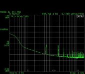
HPS 3.1 LF noise
This is the LF noise, unweighted. For measuring this, the RIAA network was pulled, the amp has an overall gain of 16550 and a BW of over 100KHz.
Noise at 1KHz is 5.18uV/rtHz divided by the gain, rendering 0.31nV/rtHz. Right on the design target.
The 60Hz odd harmonics are almost vanishing as soon as the case is closed.
Attachments
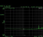
HPS 3.1 HF noise
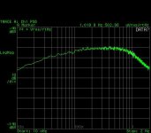
This is the HF noise, unweighted. For measuring this, the RIAA network was again pulled, the amp has an overall gain of 16550 and a BW of over 100KHz.
Noise at 10KHz is 5uV/rtHz divided by the gain, rendering 0.3nV/rtHz.
The artifact is a TV SMPS running in the house.
More measurements to follow.
This is the HF noise, unweighted. For measuring this, the RIAA network was again pulled, the amp has an overall gain of 16550 and a BW of over 100KHz.
Noise at 10KHz is 5uV/rtHz divided by the gain, rendering 0.3nV/rtHz.
The artifact is a TV SMPS running in the house.
More measurements to follow.
Attachments
Re: HPS 3.1 LF noise
Lookin' good. A couple of observation/questions, the noise getting below 100Hz or so seems to pick up to more than 1/f maybe a little GR noise. The increase at very low f could be moving air causing local thermal uncertainty. Does this get better in the box? Not that it matters, more of an instrumentation question.
syn08 said:This is the LF noise, unweighted. For measuring this, the RIAA network was pulled, the amp has an overall gain of 16550 and a BW of over 100KHz.
Noise at 1KHz is 5.18uV/rtHz divided by the gain, rendering 0.31nV/rtHz. Right on the design target.
The 60Hz odd harmonics are almost vanishing as soon as the case is closed.
Lookin' good. A couple of observation/questions, the noise getting below 100Hz or so seems to pick up to more than 1/f maybe a little GR noise. The increase at very low f could be moving air causing local thermal uncertainty. Does this get better in the box? Not that it matters, more of an instrumentation question.
Re: Re: HPS 3.1 LF noise
Most likely, this thing is running pretty hot, in particular the power buffer, which is SMD and heats up the entire board. Closing the aluminum case seems to have a limited impact, though. It could as well be the buffer noise itself...
Here's a better view of the same effect.
Now, down to 0.1nV/rtHz
scott wurcer said:
Lookin' good. A couple of observation/questions, the noise getting below 100Hz or so seems to pick up to more than 1/f maybe a little GR noise. The increase at very low f could be moving air causing local thermal uncertainty. Does this get better in the box? Not that it matters, more of an instrumentation question.
Most likely, this thing is running pretty hot, in particular the power buffer, which is SMD and heats up the entire board. Closing the aluminum case seems to have a limited impact, though. It could as well be the buffer noise itself...
Here's a better view of the same effect.
Now, down to 0.1nV/rtHz
Attachments
Re: HPS 3.1 LF noise
Nope, I don't think it's a thermal effect... It seems like after bumping around 1Hz the spectral density at 100mHz more or less goes back to 1/f, the physics is saved!
At this point I suspect the power supply, namely the power MOSFETs used all along. It's mostly academic, but nonetheless interesting... I'll let it overnight to get a few 10mHz averaged measurements.
Attachments
- Status
- This old topic is closed. If you want to reopen this topic, contact a moderator using the "Report Post" button.
- Home
- Source & Line
- Analogue Source
- GPP - Great Phono Preamp