Hi syn,
thanks a lot for your reply. I hope you don't mind discussing some more practical issues here.
In your schematic you specify the fets running at around 4.5mA. The Fets I have happen to be around 7-8mA IDSS, so might settle around 6mA with 2.2 Rs.
What is the usable range, before Q203/205 will starve out for current? What is the supply voltage out of the reg, +/-15V? What is the optimal/targeted current feed for Q203/205?
I cannot see any reasons not to use LM49710 for U203/U204, which I already have, or are there any? Maybe it's just me, but I found them to sound better in a riaa app and less prone to instability as well.
Thanks again,
Rüdiger
Hi syn,
thanks a lot for your reply. I hope you don't mind discussing some more practical issues here.
In your schematic you specify the fets running at around 4.5mA. The Fets I have happen to be around 7-8mA IDSS, so might settle around 6mA with 2.2 Rs.
What is the usable range, before Q203/205 will starve out for current? What is the supply voltage out of the reg, +/-15V? What is the optimal/targeted current feed for Q203/205?
I cannot see any reasons not to use LM49710 for U203/U204, which I already have, or are there any? Maybe it's just me, but I found them to sound better in a riaa app and less prone to instability as well.
Thanks again,
Rüdiger
All excellent questions.
1. JFETs should be around max 8mA Idss. If more, indeed there's a risk of starving Q203/Q205. If JFETs have more than 8mA Idss, you may want to adjust R203/R237 and increase a little the current through R202/R240
2. There is no strict bias for Q203/Q205. 3-5mA or more is ok, but don't over do it, otherwise you'll have to manage the heat.
3. The supply voltages are +/-22V
4. You need opamps that support +/-22V. LME49710 usually are fine (I tried them myself), but you are outside the data sheet specs, so no guarantees. Nat Semi is manufacturing an excellent +/-22V audio opamp (LME49870) but unfortunately it comes in SMD only, so you need adapters. My suggestion would be to install DIP sockets, you may decide later what opamps you like. BTW, from the datasheets, it looks like LME49870 is nothing but LME49710 tested and guaranteed at +/-22V.
Last edited:
Hi.
I'm fighting with the placement of the input fet's. The photo on your website gives the imagination, that whether the p-fets are placed near the positive rail or the fets are reversed (beeing d-g-s at front view, as opposed to s-g-d for the 2sk246). I know that the 2sk170's work when reversed, but I'd like to know what is going on there. For sure, I need a break...
Rüdiger
Hi.
I'm fighting with the placement of the input fet's. The photo on your website gives the imagination, that whether the p-fets are placed near the positive rail or the fets are reversed (beeing d-g-s at front view, as opposed to s-g-d for the 2sk246). I know that the 2sk170's work when reversed, but I'd like to know what is going on there. For sure, I need a break...
Rüdiger
Attachments
Syn08,
thanks a lot. According to the datasheet, they are reversed. The 2sj103 in the regulator are placed the right way round, and compared to the 170's, the pins are swapped.
The 170's do definitly work 'backwards', but I don't know if that is really aquivalent spec- and soundwise.
Rüdiger
thanks a lot. According to the datasheet, they are reversed. The 2sj103 in the regulator are placed the right way round, and compared to the 170's, the pins are swapped.
The 170's do definitly work 'backwards', but I don't know if that is really aquivalent spec- and soundwise.
Rüdiger
The 170's do definitly work 'backwards', but I don't know if that is really aquivalent spec- and soundwise.
It doesn't matter, but if you have any doubts, just install the 2SK170/2SJ74 rotated by 180 (swap D and S).
syn08,
Would I be correct in assuming that you matched Idss on the input stage JFETs? If so how accurately did you find it necessary to match them? Did you match any other parameters?
Thanks in advance.
You don't have to match them at all; just use the BL class out of the tube, the servo is taking care of the offset due to any mismatch. OTOH, matching JFETs has absolutely no impact on the overall noise. High Idss devices won't do any good in terms of performance, but if it happens to get parts with an average Idss over 8mA, then you may need to increase a little the current through R202/R240 by adjusting R203 and R241. Don't do this without any good reason, it will only increase the power dissipation in Q203/Q205 (currently running in free air, no heatsink is required).
LP797 by Dennis Colin
Hi Syn08
A bit late by now, I admit. But your work on the LP797 is very interesting, corresponding to my ideas entirely. How has things progressed ?
Do you have any PCB's / schematics / partslist ?
As you probably know, I recently decided it's time to enjoy my old vinyl collection. I got a VPI HW-19 MK3 (which I eventually upgraded to the Scout platter and bearing), with AudioQuest PT-9 tonearm and Benz Micro Silver cartridge. I got originally a NAD PP3 phono preamp, paying $150 for essentialy a couple of 5532 opamps in a small metal case. After a little listening, I was having difficulties plotting the fastest course to BayBloor Radio to return the thing...
So, not willing to pay $1000+ for what it is supposed to be a decent phono stage, I decided to DIY one. The other good reason was to finally do some decent comparison between a fully IC based solution (around the new OPA827) and a hybrid solution (2SK170 input stage plus gain opamps). Originally I was planning to start with the full IC design, but some discussions on this forum made me decide to start with the hybrid beast.
Dennis Colin's implementation published in AudioExpress "The LP 797 Ultra-Low Distortion Phono Preamp" audioXpress - Articles and Addenda with a few tweaks is the core signal chain. This implementation has a serious problem though: the PSRR is very poor. Colin tried to mitigate this issue with a primitive power supply and a 10,000uF capacitor on the input stage power rail, which is obvious a poor solution. So I've decided to add a Jung super regulator on the same board, together with a TLE2426 rail splitter/virtual ground. I've also decided to put all opamps on sockets, to be able to evaluate the measured and sonic results.
I gave up the idea to switch the input with some fancy Panasonic relays mostly because I was unable to find any good reason why to read a MC cartridge with a 200ohm input impedance. This being said, for switching the gain (MC/MM) in the second stage (where everything is already at 20-30mV) and muting the output I was able to use the same cheap (but not poor) Hamlin reed relays that PGP uses on the input.
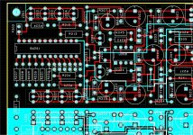
Here's a picture of the finished board. The metal case is waiting for drilling (will happen tomorrow) then the evaluation will start. From what I was able to quickly measure on the board, it's stable with AD797, OPA627 and LME49710, RIAA is +/-0.1dB (but I had to sort the RC's to better than 0.5% nominal and to 0.1% between channels). Noise is around 1nV/rtHz with AD797 in the input stage loop (I'll confirm this after the whole thing is cased and properly grounded).
Will be back in the following days (and of course on my web site, which God knows when I'll find the time to update) with schematics (nothing really spectacular) the implementation (I think the layout is very good) and the measurement and sonic details. Now I need some sleep.
Hi Syn08
A bit late by now, I admit. But your work on the LP797 is very interesting, corresponding to my ideas entirely. How has things progressed ?
Do you have any PCB's / schematics / partslist ?
LP 797... better late than never
Hi Syn08,
I just saw the original article by Dennis Colin yesterday. I then found your WEB site with all of the upgrades. Great. However I have a very basic question. I am confused with Mr. Colin's use of S1A to swith MM and MC. The schematic, to me ay least, switches MM and MC to the same connection. Where is the gain change? I am also, I apologize, lost to where you are switching MM and MC.
I do hope you catch this late message. I may need to open a new thread which I do not want to do.
If you (or someone reading) would be so kind as to explain/show where the different connections are.
Thanks much,
Bruce
LP797 MC/MM
Thanks PMA. Sad to hear. Well, I viewed all previous posts came up with this:
"for switching the gain (MC/MM) in the second stage (where everything is already at 20-30mV)" he mentions a relay which I see on his schematic and it is not clear to me.
Oh well...if some patient person can spell it out for me, great. When I see Mr. Jung's phono pre using LT1115 in the data sheet for LT1115, switching in/out MM and MC makes total visual and electronic sense to me.
Again, any one else wants to take a shot, I would appreciate it.
Bruce
No problem.
You could have figured yourself that the gain should differ 10x (20dB)
Afair, the value across the opamp is 1K.
say : R1 is the always-in gain setting resistor for MM.
And R2 for the switched one.
Gain MM : 1K/R1 + 1
1/R3 = 1/R1 + 1/R2
Gain MC : 1K/R3 + 1
(afair from Mr Colin's article, gain difference between the MM and MC setting is 19.93dB)
Last edited:
- Status
- This old topic is closed. If you want to reopen this topic, contact a moderator using the "Report Post" button.
- Home
- Source & Line
- Analogue Source
- GPP - Great Phono Preamp