Do you mean why I select the FET 2N3369?
You know, Tina-TI have very little FET to let me select.
I just chose one which can work.
Usually I will consider about noise for input stage.
thanks, that makes sense.
wouldn't the 2N3369 have a wider bandwidth than the opa549? doesn't this make it the circuit susceptible to the same problems we needed to compensate for when using the OPA1632?
Yes, it is.wouldn't the 2N3369 have a wider bandwidth than the opa549? doesn't this make it the circuit susceptible to the same problems we needed to compensate for when using the OPA1632?
So the input buffers maybe better.
Will this new chip be usable ultrasymetrically?
LME49990 - Ultra-low Distortion, Ultra-low Noise Operational Amplifier
LME49990 - Ultra-low Distortion, Ultra-low Noise Operational Amplifier
Yes, It can be usable ultrasymetrically. I think.Will this new chip be usable ultrasymetrically?
LME49990 - Ultra-low Distortion, Ultra-low Noise Operational Amplifier
I wanted to see what i could learn about Wen-San's design by doing some modeling.
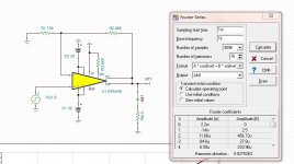
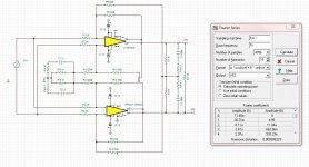
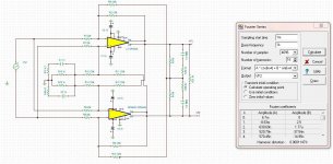
The first question I addressed is: What is the THD in the opa549 in a standard non-inverting configuration and Wen-San's design.
The difference in THD between the two circuits is significant enough that it it seems likely that the result would carry over to a real circuit.
The first question I addressed is: What is the THD in the opa549 in a standard non-inverting configuration and Wen-San's design.
The difference in THD between the two circuits is significant enough that it it seems likely that the result would carry over to a real circuit.
Attachments
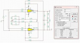
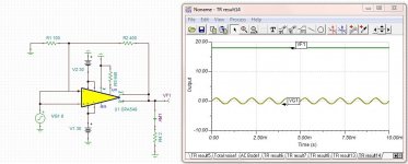
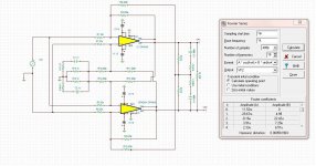
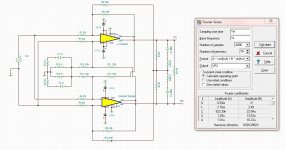
I next wanted to investigate how sensitive the circuit was to ground noise. The standard instrument amp circuit only has a virtual ground, however, Wen-San's design gives up the virtual ground for a real one.
I tried a very large ground "noise" (1V amplitude 2khz).
It increased THD, but given the amount of ground "noise", I'd say the circuit is quite insensitive.
I tried a very large ground "noise" (1V amplitude 2khz).
It increased THD, but given the amount of ground "noise", I'd say the circuit is quite insensitive.
Attachments
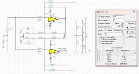
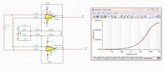
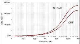
Finally I wanted to look at the effect of common mode feedback (CMF) on Total Noise.
I simply removed the common mode feedback from the circuit to make the comparison.
I also wanted to see how sensitive Total Noise was to small variations in resistor value so I adjusted the 200K resistors randomly between 199 and 201 K. This change did not effect the Total Noise measurement.
I suppose the true test would be to put some common mode noise at the input. I still need to figure out how to do this but I wouldn't mind if someone beat me to it.
Attachments
CMMR tests
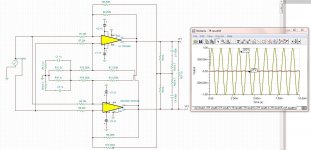
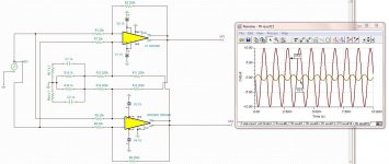
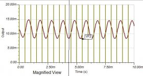
Below I've attached the the common mode response of 3 different configurations:
1. standard non inverting OPA549 (same gain as other configs)
2. Wen-San config without common mode feedback
3. Wen-San config with common mode feedback
in all cases the input is 1V, 1khz to both the inverting and non inverting inputs.
the final image is a magnified view of the transient response shown in 3.
Attachments
-
 OPA549 - Wen-San - cmf - Transient with cm input.jpg206 KB · Views: 253
 -
 OPA549 - Wen-San - No cmf - Transient with cm input.jpg173.7 KB · Views: 231
 -
 OPA549 - standard config - Transient with cm input.jpg78.3 KB · Views: 243
 -
 OPA549 - Wen-San - cmf - Transient with cm input - magnified view.jpg31.2 KB · Views: 240
Very good simulations and analyses.
I couldn't do batter.
thanks!
i think it may be almost time for me to start building but first i need to decide on an input buffer (I'm not going to go with nested feedback).
for the buffer, i could just use a single op amp but i guess there would be an advantage to using a differential input?
i will probably also design a circuit board.
Tim
Last edited:
Mark Levinson No.380 preamplifier use this cricuit in front of the fully differential circuit.for the buffer, i could just use a single op amp but i guess there would be an advantage to using a differential input?
An externally hosted image should be here but it was not working when we last tested it.
It can provide some gain, so you can reduce the gain of the fully differential circuit.
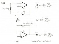
I think I need my input stage to handle the single ended to balanced conversion.
With the circuit posted immediately above i can obtain conversion by making Vi2 a ground.
I also found a (see below) variation on the above circuit in Jerald Graeme's book: Amplifier applications of op amps. It removes some of the common mode signal that that the above circuit can create but it only works for gains of 3 or higher.
On a separate but related topic, it seems that lowering the gain of Wen-San's circuit with OPA549 caused THD to rise.
Attachments
Maybe or maybe not.On a separate but related topic, it seems that lowering the gain of Wen-San's circuit with OPA549 caused THD to rise.
I noticed that.
If you measure THD by a unbalance signal,
The THD variation seems noticeable,
Because the feature of balance is different.
But the THD variation of balance signal seems not very noticeable.
So, the common mode feedback resistors should be adjusted at the same time.
Maybe or maybe not.
I noticed that.
If you measure THD by a unbalance signal,
The THD variation seems noticeable,
Because the feature of balance is different.
But the THD variation of balance signal seems not very noticeable.
So, the common mode feedback resistors should be adjusted at the same time.
Not surprisingly, you are correct. Lower gain and a balanced input gives the best THD performance (see pics below).Thank you.
For an input buffer i have on hand OPA1632 and LM49710 - any suggestions on how to use them together to make the output more than the sum of the parts?
Attachments
May I humbly ask of the brilliant people here, some help with this thread?: http://www.diyaudio.com/forums/chip-amps/158644-12v-dc-gainclone-2.html
We need about a 10k input impedance, and either to get TDA1588Q to work right or to come up with a nice simple bridged LM1875 design (with one chip inverting and the other non-inverting). The power is 12vdc to 16vdc. Its a starter project, but TDA1588q was a "non starter" because of noise output. help?
We need about a 10k input impedance, and either to get TDA1588Q to work right or to come up with a nice simple bridged LM1875 design (with one chip inverting and the other non-inverting). The power is 12vdc to 16vdc. Its a starter project, but TDA1588q was a "non starter" because of noise output. help?
Last edited:
Hi zei,
here is the schematic with fully-differential (balanced) input.
I left out the PS coupling parts and pinout of chips, you have them in schematic in post #672.
Some part values are different in this new sch. - don't worry about that, the amp sounds better this way.
Cheers !
Juma,
I would like to build this amp to drive some monitor speakers and have a question. THis is my first opamp amp and i also new to SMD chips so i am unsure abou the different offerings available from digikey and mouser. Which designation do i need and what is different about them. On the surface, they all seem to be the same, but i know there must be something different. I am assuming the DGN version with the "powerpad" does better with heat, is this necessary?
You do not need the power pad version (DGN). We have been using the OPA1631/THS4131 in this manner for years, in several products without issues. We only use the SOIC package (D & DGx). I believe the power pad is only needed to compensate for the small die size of the MSOP package.
THanks. I find it interesting that you use a slightly different version. May i ask why. I have heard so much about the 1632.
Sorry, pre-coffee typo. OPA1632.
...Which designation do i need ...
As Brian said, THS4131 in the SOIC package is a good choice. It's bigger, easier to manipulate.
- Status
- This old topic is closed. If you want to reopen this topic, contact a moderator using the "Report Post" button.
- Home
- Amplifiers
- Pass Labs
- GC SuperSymmetry