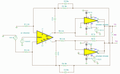
wensan, please read Walt Jung's papers on composite amplifier, you'll see that "contradiction" you mention is actually quite beneficiary.I don't think using OPA1632 to drive 2 OPA549 is a good idea.
The slew rate of OPA1632 is 50 V/us.
The slew rate of OPA549 is only 9 V/us.
There is a contradiction on speed, and there is a stability issue apparently.
You should consider that fact having a GBW product in mind....
The open loop gain of OPA549 is 100 dB.
....
BTW, both chips (1632 and 549) are very stable in unity gain configuration.
I mean the OPA549 will be a limit to the OPA1632 on speed and stability.wensan, please read Walt Jung's papers on composite amplifier, you'll see that "contradiction" you mention is actually quite beneficiary.
Since the OPA549 is a limit to the OPA1632, the GBW of the OPA1632 have to be reduce by the stability compensation.You should consider that fact having a GBW product in mind.
I don't really like it, but it will work anyway.
When the inner device has more bandwidth than the outer device, some of the inner devices open loop gain can be used to extend the bandwidth of the outer device.
When the outer device has more bandwidth than the inner device, the bandwidth of the outer device must be reduced to prevent oscillation. In this configuration you are losing one of the main benefits of a composite amplifier, but I think we are forced in this direction if all of the available output devices that are powerful enough to drive a loudspeaker are bandwidth limited. The only high current, current feedback op amp I know of is the LT1210 (min 1.1 amp, typical 2amp, from memory) and you would need a very efficient speaker to make this work unless you want to consider paralleling devices.
Can you guys confirm my thinking on this topic? Can you also discuss what benefits remain when the outer device is bandwidth limited in a composite layout.
Wen-San, if you don't like Juma's amp you really won't like:
Sympatico Amplifier
Last edited:
A power buffer with the slew rate higher than 50 V/us is easy to build by discrete parts.
The slew rate of a signal will be amplify by a amplifier.
It means, If the slew rate limit of OPA549 is 9 V/us, and the gain of OPA549 is 2,
then the slew rate of the OPA549's input signal should be limit to below 4.5 V/us.
Otherwise, the TIM(Transient Intermodulation Distortion) and SID(Slew Induce Distortion) will occur.
But the OPA1632 has 50 V/us of slew rate, it is too high to the input signal of the OPA549.
So the slew rate of the OPA1632 must be reduced to below 4.5 V/us.
The formula of OP's slew rate limit is SR = 2 Pi Vth GBP. The Vth of OPA1632 can not be changed.
So the GBP of OPA1632 have to be reduced to 0.09 GBP by compensation.
In the meantime, I have to apologize.
I didn't mean to offend anyone.
I have only college degree in Taiwan.
My English is too awful to read a professional paper such like Walt Jung's.
I don't qualify to comment other's design.
I will not comment other's design again.
I apologize sincerely.
Attachments
Last edited:
.......
I don't qualify to comment other's design.
I will not comment other's design again.
I apologize sincerely.
wensan - you are certainly qualified enough ( just being a member ) to express your opinion .
it really doesn't matter is your ( or anyone else's) opinion technical correct .
in that way we all are learning - through dialog .
Last edited:
It would be proper explanation if we were talking about motor engine and gears,...
But the OPA1632 has 50 V/us of slew rate, it is too high to the input signal of the OPA549. ...
but it doesn't work that way with electrical signals.
There is no need to reinvent the wheel, Walt Jung (composite amplifier) and Nelson Pass (SuperSymmetry patent) explained why this amplifier sounds way better than single OPA549.
Knowledge of English language you demonstrated here is certainly good enough to understand aforementioned papers - don't give up so easily
")
Last edited:
I had read a Chinese translation of Walt Jung's "Overview of SID and TIM" on an audio magazine in Taiwan about 30 years ago.
I was about the age of a highschool student at that time.
Overview of SID and TIM Part 1
Overview of SID and TIM Part 2
Overview of SID and TIM Part 3
The Walt Jung's "Overview of SID and TIM" explains the slew rate issue of an amplifier very clearly.
I found the slew rate limit formula in this article.
Back to the circuit that using OPA1632 drive 2 OPA549.
If we focus on OPA549's part,
The OPA549's part is a invert amplifier circuit completely and independently.
If we apply the theory of Walt Jung's "Overview of SID and TIM" to the OPA549's part,
The conclusion is the slew rate of the OPA549's input signal should be limit to below 4.5 V/us.
Otherwise, the TIM(Transient Intermodulation Distortion) and SID(Slew Induce Distortion) will occur.
Then,
If we focus on OPA1632's part,
The OPA1632's part is not a complete feedback amplifier circuit !
If the OPA1632's output signals haven't go through the OPA549's part,
The OPA1632 can not get its feedback signals.
When the OPA1632 hasn't gotten its feedback signals yet,
The OPA1632's output will drive at full speed, that means 50 V/us.
But we have already gotten the conclusion that the slew rate of the OPA549's input signal should be limit to below 4.5 V/us.
So the OPA1632's slew rate limit have to be reduced to below 4.5 V/us.
According to the slew rate limit formula what I found in Walt Junf's article.
The OPA1632's GBP have to be reduced to below 0.09 GBP by compensation.
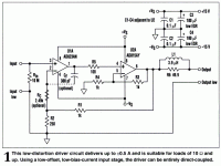
This is the other Walt Jung's article "Composite Line Driver with Low Distortion".
Composite Line Driver with Low Distortion
Although so many English words make me dizzy.
But I still can look at the figure and guess.
The example in this article using AD823AN to drive AD815AY, the AD815AY's gain is 2.
The AD815AY's slew rate limit is 900 V/us.
So the AD815AY's part can accept 450 V/us of input signal slew rate.
The AD823AN's slew rate limit is 22 V/us.
I don't see the contradiction on Walt Jung's example.
I was about the age of a highschool student at that time.
Overview of SID and TIM Part 1
Overview of SID and TIM Part 2
Overview of SID and TIM Part 3
The Walt Jung's "Overview of SID and TIM" explains the slew rate issue of an amplifier very clearly.
I found the slew rate limit formula in this article.
Back to the circuit that using OPA1632 drive 2 OPA549.
If we focus on OPA549's part,
The OPA549's part is a invert amplifier circuit completely and independently.
If we apply the theory of Walt Jung's "Overview of SID and TIM" to the OPA549's part,
The conclusion is the slew rate of the OPA549's input signal should be limit to below 4.5 V/us.
Otherwise, the TIM(Transient Intermodulation Distortion) and SID(Slew Induce Distortion) will occur.
Then,
If we focus on OPA1632's part,
The OPA1632's part is not a complete feedback amplifier circuit !
If the OPA1632's output signals haven't go through the OPA549's part,
The OPA1632 can not get its feedback signals.
When the OPA1632 hasn't gotten its feedback signals yet,
The OPA1632's output will drive at full speed, that means 50 V/us.
But we have already gotten the conclusion that the slew rate of the OPA549's input signal should be limit to below 4.5 V/us.
So the OPA1632's slew rate limit have to be reduced to below 4.5 V/us.
According to the slew rate limit formula what I found in Walt Junf's article.
The OPA1632's GBP have to be reduced to below 0.09 GBP by compensation.
This is the other Walt Jung's article "Composite Line Driver with Low Distortion".
Composite Line Driver with Low Distortion
Although so many English words make me dizzy.
But I still can look at the figure and guess.
The example in this article using AD823AN to drive AD815AY, the AD815AY's gain is 2.
The AD815AY's slew rate limit is 900 V/us.
So the AD815AY's part can accept 450 V/us of input signal slew rate.
The AD823AN's slew rate limit is 22 V/us.
I don't see the contradiction on Walt Jung's example.
Attachments
wensan - you are certainly qualified enough ( just being a member ) to express your opinion .
it really doesn't matter is your ( or anyone else's) opinion technical correct .
in that way we all are learning - through dialog .
No, I don't see any technical controvert.
I only see the controvert that tell me go back to read and learn.
And I think I should.
...
The OPA549's part is a invert amplifier circuit completely and independently.
...
Sorry, but we can not consider opa549 completely independently because it is included into feedback loop of the opa1632, so output signal from opa549 is going to return to opa1632's input.
You see how nested loops are fun !
BTW, why are you so obssesed with slew rate - it really isn't that important...
Last edited:
It occurred to me that I might harm somebody's business.Wen-San, if you don't like Juma's amp you really won't like:
Sympatico Amplifier
I didn't mean to do that.
I apologize deeply.
I never mention about engine and gears,It would be proper explanation if we were talking about motor engine and gears,
but it doesn't work that way with electrical signals.
"To divert the focus" is a trick of sophistry.
I have my own explanation to tell the difference between balance and unbalance signals,There is no need to reinvent the wheel, Walt Jung (composite amplifier) and Nelson Pass (SuperSymmetry patent) explained why this amplifier sounds way better than single OPA549.
Although it's in Chinese. ż´ÎÖC²¨Ê§ÕæÅcÆæ´ÎÖC²¨Ê§Õæ - ÒôÏìDIYÂÛ̳ - HIFIDIYÂÛ̳ - Powered by Discuz!
I wonder where is your own theory?
The OPA549's part can work independently.Sorry, but we can not consider opa549 completely independently because it is included into feedback loop of the opa1632, so output signal from opa549 is going to return to opa1632's input.
You see how nested loops are fun !
It is an independent object at the bottom of the nest.
The slew rate issue is important enough that Walt Jung had spent so much time to reason and experiment and write such a long article to explain it.BTW, why are you so obssesed with slew rate - it really isn't that important...
I wonder don't you read Walt Jung's papers ?
Then why you ask me to read Walt Jung's papers ?
The Burr-Brown app note (http://focus.ti.com/lit/an/sboa002/sboa002.pdf) has a relevant comment on the advantages of the composite configuration when the bandwidth of the two devices is equal:
"If the bandwidth and settling time advantages of the composite amplifier are needed, but not the slew rate boost, it is possible to make a composite amplifier using a dual op amp such as the OPA2107 as shown in Figures 3 and 4. It is best to use a dual op amp because of the inherent matching of dynamic characteristics. To ensure stability and the best transient response, set the gain of A1(outer loop op amp) two times the gain of A2 (inner loop op amp)"
My questions are:
1. Does the OPA549's bandwidth and settling time improve significantly when inside the OPA1632's feedback loop?
2. Is a another advantage the thermal isolation of the OPA1632 from the OPA549?
I don't think we(maybe just me) have enough resource to do precise experiment and measurement in real world to answer your questions.The Burr-Brown app note (http://focus.ti.com/lit/an/sboa002/sboa002.pdf) has a relevant comment on the advantages of the composite configuration when the bandwidth of the two devices is equal:
"If the bandwidth and settling time advantages of the composite amplifier are needed, but not the slew rate boost, it is possible to make a composite amplifier using a dual op amp such as the OPA2107 as shown in Figures 3 and 4. It is best to use a dual op amp because of the inherent matching of dynamic characteristics. To ensure stability and the best transient response, set the gain of A1(outer loop op amp) two times the gain of A2 (inner loop op amp)"
My questions are:
1. Does the OPA549's bandwidth and settling time improve significantly when inside the OPA1632's feedback loop?
2. Is a another advantage the thermal isolation of the OPA1632 from the OPA549?
Simulation may help.
My experience is if simulation isn't successful, it means there is unexpected something very difficult to calculate.
So the "something" is a problem of circuit.
The most difficult part is how to figure out what is the "something".
A power buffer with the slew rate higher than 50 V/us is easy to build by discrete parts.
The slew rate of a signal will be amplify by a amplifier.
It means, If the slew rate limit of OPA549 is 9 V/us, and the gain of OPA549 is 2,
then the slew rate of the OPA549's input signal should be limit to below 4.5 V/us.
Otherwise, the TIM(Transient Intermodulation Distortion) and SID(Slew Induce Distortion) will occur.
But the OPA1632 has 50 V/us of slew rate, it is too high to the input signal of the OPA549.
So the slew rate of the OPA1632 must be reduced to below 4.5 V/us.
The formula of OP's slew rate limit is SR = 2 Pi Vth GBP. The Vth of OPA1632 can not be changed.
So the GBP of OPA1632 have to be reduced to 0.09 GBP by compensation.
Operating the OPA549 at a unity would get the most bandwidth (900khz) out of this configuration.
I realize that even at unity there is still the possibility for slew rate distortion because of the higher slew rate of the 1632, but at some frequency, even the slewed output must well above audible frequencies?
I need to read more about TIM before I can comment.
Is Vth the peak voltage?
Wen-San, thanks for your feedback.
You have to analyze the slew rate issue by transient state, not steady state.Operating the OPA549 at a unity would get the most bandwidth (900khz) out of this configuration.
I realize that even at unity there is still the possibility for slew rate distortion because of the higher slew rate of the 1632, but at some frequency, even the slewed output must well above audible frequencies?
The slew rate issue is about the delay of feedback signal.
If OP amplifier hasn't gotten its feedback signal, it will amplify input signal by full open loop gain.
The Vth of OP amplifier is the maximum differential input signal that the OP amplifier can accept(between positive and negative input pins).Is Vth the peak voltage?
The Vth also call IDR(Input Dynamic Range).
Sorry! My English is poor.but at some frequency, even the slewed output must well above audible frequencies?
I try to understand the meaning you said.
Do you mean the frequency of TIM distortion ingredient will be higher than audible frequencies?
But TIM distortion is some kind of IM distortion,
It means TIM distortion ingredient is "beat note". (I found "beat note" from wikipedia)
The frequency of "beat note" will be lower than the original signals.
Operating the OPA549 at a unity would get the most bandwidth (900khz) out of this configuration.
The "small signal bandwidth" and the "power bandwidth" are two total different things.
The "small signal bandwidth" is limited by stability.
But the "power bandwidth" is limited by slew rate and maximum output voltage.
Usually, when we say "bandwidth", it means the "small signal bandwidth".
Because we must designate the maximum output voltage,
Then we can calculate the "power bandwidth" by slew rate.
So, If slew rate is 9 V/us, the maximum output voltage is 15V,
Then the "power bandwidth" will be about 95 KHz.
Last edited:
- Status
- This old topic is closed. If you want to reopen this topic, contact a moderator using the "Report Post" button.
- Home
- Amplifiers
- Pass Labs
- GC SuperSymmetry