I am always pleased when this thread lurches back to life.

Hehehe...I remember the day when this thread was started. I was at the seaside, having a break (from amps, forum, studying...), but couldn't resist sneaking into the forum for just a couple of minutes...and saw THIS thread!
Splash! I remember like it was just yesterday!
Juma,
I've been thinking about what amp to build for the LP section of the bi-amping project I'm working on, and browsing this thread I just saw your schematic on post #682 here. I agree with Carl_Huff when he says it deserves it's own thread; although I understand why you don't want to write it all twice, for those of us who can't read Serbian it would be a big help...
It certainly looks a lot more interesting than a datasheet-based LM3886 solution that I was considering...
In any event, since I (at least) can't read Serbian, may I ask a couple of questions ? (Probably stupid ones, but you're probably used to that from me by now... )
1. You say above you use this without the input section, after your BF862 preamp without output cap, but with another buffer... If you *had* an output cap on the preamp you would just connect to the 3k3 resistor on pin 8 of the OPA1632, correct? Your schematic for the BF862 preamp *has* cap on the output, so I presume you're using an altered version? (Or did I miss something? - quite possible...)
2. Since your circuit uses the inverting outputs of the OPA549s, am I right in thinking this would have to be inverted again to bi-amp with a non-inverting amp on the HP section? (Such as F5, which is my plan...) Can your schematic be altered in any simple way to give a non-inverting output?
3. How much power should this give into a 4 ohm speaker? (I may be stuck using a car audio (sub)woofer for bass...)
Cheers
Nigel
I've been thinking about what amp to build for the LP section of the bi-amping project I'm working on, and browsing this thread I just saw your schematic on post #682 here. I agree with Carl_Huff when he says it deserves it's own thread; although I understand why you don't want to write it all twice, for those of us who can't read Serbian it would be a big help...
It certainly looks a lot more interesting than a datasheet-based LM3886 solution that I was considering...
In any event, since I (at least) can't read Serbian, may I ask a couple of questions ? (Probably stupid ones, but you're probably used to that from me by now...
)1. You say above you use this without the input section, after your BF862 preamp without output cap, but with another buffer... If you *had* an output cap on the preamp you would just connect to the 3k3 resistor on pin 8 of the OPA1632, correct? Your schematic for the BF862 preamp *has* cap on the output, so I presume you're using an altered version? (Or did I miss something? - quite possible...)
2. Since your circuit uses the inverting outputs of the OPA549s, am I right in thinking this would have to be inverted again to bi-amp with a non-inverting amp on the HP section? (Such as F5, which is my plan...) Can your schematic be altered in any simple way to give a non-inverting output?
3. How much power should this give into a 4 ohm speaker? (I may be stuck using a car audio (sub)woofer for bass...)
Cheers
Nigel
Hi zei,
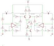
here is the schematic with fully-differential (balanced) input.
I left out the PS coupling parts and pinout of chips, you have them in schematic in post #672.
Some part values are different in this new sch. - don't worry about that, the amp sounds better this way.
Cheers !
Hi Juma,
that schematic makes me think you have been modeling the circuit.
1. would you mind posting your model file?
2. do you get different % distortion on the outputs?
Thanks,
Tim
the problems i was having earlier with peaking were related to using the OPA1632 model that is preloaded into TINA-TI. When i switched to the latest version downloaded from the OPA1632 page the problem disappeared.
Hi Okapi,Hi Juma,
that schematic makes me think you have been modeling the circuit.
1. would you mind posting your model file?
2. do you get different % distortion on the outputs?
I used Tina just for quick schematic drawing (free version won't let me simulate the circuit with more than two ICs).
There you have it - all that simulations are not really reliable (except for really simple circuits - but you don't need complex sim software for them). Nothing beats the old school - built it and tune it...When i switched to the latest version downloaded from the OPA1632 page the problem disappeared.
BTW, you can use the THS4131 chip, it's practically the same thing as OPA1632.
Correct. Preamp has the buffer on its output so we don't need another one on amp's input (I suppose that master volume pot is before the active x-over ?), but we do need a coupling cap since preamp's buffer output sits on +12V DC...
1. You say above you use this without the input section, after your BF862 preamp without output cap, but with another buffer... If you *had* an output cap on the preamp you would just connect to the 3k3 resistor on pin 8 of the OPA1632, correct?
You got to have it somewhere, take your pick, the only thing you shouldn't do is to let the DC voltage enter the amp through the input connection......
Your schematic for the BF862 preamp *has* cap on the output, so I presume you're using an altered version? (Or did I miss something? - quite possible...)
It's irrelevant - you can easily trace the phase polarity through the whole circuit and turn the speakers right way around since neither end of the speaker touches the ground connection....
2. Since your circuit uses the inverting outputs of the OPA549s, am I right in thinking this would have to be inverted again to bi-amp with a non-inverting amp on the HP section? (Such as F5, which is my plan...)
Can your schematic be altered in any simple way to give a non-inverting output?
Yes, OPA549 can be easily used here in non-inverting mode but I find that it makes it sound inferior.
With +/-20V PS the SuSy configuration (fundamentally, it's a bridge) will give you about 100W RMS max. on the 4 ohms speaker....
3. How much power should this give into a 4 ohm speaker? (I may be stuck using a car audio (sub)woofer for bass...)
An externally hosted image should be here but it was not working when we last tested it.
An externally hosted image should be here but it was not working when we last tested it.
The Close Loop Common Gain still remain 1.
An externally hosted image should be here but it was not working when we last tested it.
An externally hosted image should be here but it was not working when we last tested it.
An externally hosted image should be here but it was not working when we last tested it.
An externally hosted image should be here but it was not working when we last tested it.
The Close Loop Common Mode Gain is not suppressed.
An externally hosted image should be here but it was not working when we last tested it.
An externally hosted image should be here but it was not working when we last tested it.
Separate it symmetrically become a Fully Differential Amplifier with Common Mode Feedback.
An externally hosted image should be here but it was not working when we last tested it.
Last edited:
I had built such "Ultra Symmetry" circuit as a pre-amplifier and a power amplifier in Taiwan 5 years ago!
An externally hosted image should be here but it was not working when we last tested it.
An externally hosted image should be here but it was not working when we last tested it.
An externally hosted image should be here but it was not working when we last tested it.
An externally hosted image should be here but it was not working when we last tested it.
An externally hosted image should be here but it was not working when we last tested it.
An externally hosted image should be here but it was not working when we last tested it.
An externally hosted image should be here but it was not working when we last tested it.
An externally hosted image should be here but it was not working when we last tested it.
An externally hosted image should be here but it was not working when we last tested it.
An externally hosted image should be here but it was not working when we last tested it.
A piece of cake!
yeah ....... certainly - piece of cake ........ box .
Dangerous?It has occurred to me previously that you are a dangerous
guy to have loose, Wen-san.
Do you mean I shouldn't announce such research that I had researched for decades when I was a student?
Dangerous?
Do you mean I shouldn't announce such research that I had researched for decades when I was a student?
Nelson was giving you the ultimate compliment.
Please don't hesitate to "announce" all your relevant research or post some schematics
It was indeed a compliment.
I don't see any reason why you shouldn't share your work.
Thanks.
I am so timid.
Juma amp TINA-TI simulation
I've attached the simulation file for JUMA's schematic. I think you can simulate more than two IC's as I have it working with 3. This is my first attempt at computational modeling so any and all advice would be appreciated.
In the model, I've found that placing the cap in parallel with Rf gives better compensation (phase response) than placing the cap across the input in/out of the OPA1632 (I am making no claims about the audibility of the two options). I believe this is what Jerald Graeme recommends. Mr Graeme, as far as i can tell, has published the most on composite amplifiers. His work is still a bit over my head, consequently, you may not want to take my word for it. You can find a bunch of app notes by Graeme on the TI site. They were originally Burr Brown app notes. He also has a book chapter dedicated to the topic (Amplifier applications of OP AMPS).
In any case, I have both caps in the model. Just set one pair to zero while playing with values for the other pair.
Another difference you may notice in the model is that I am not using a 10k resistor around the OPA549. I obtained better distortion numbers (and i thought, fewer error messages, see below) with a lower gain around the OPA549. Feel free to experiment, I'd be curious to see what others come up with.
One final note is that i often got an error when generating a bode plot using the menu option: AC transfer characteristic. I cannot explain the error - it comes and goes randomly (Very Frustrating). I can always generate a transient response or Fourier analysis.
Almost time to start building.....
Attachments
I've attached the simulation file for JUMA's schematic. I think you can simulate more than two IC's as I have it working with 3. This is my first attempt at computational modeling so any and all advice would be appreciated.
In the model, I've found that placing the cap in parallel with Rf gives better compensation (phase response) than placing the cap across the input in/out of the OPA1632 (I am making no claims about the audibility of the two options). I believe this is what Jerald Graeme recommends. Mr Graeme, as far as i can tell, has published the most on composite amplifiers. His work is still a bit over my head, consequently, you may not want to take my word for it. You can find a bunch of app notes by Graeme on the TI site. They were originally Burr Brown app notes. He also has a book chapter dedicated to the topic (Amplifier applications of OP AMPS).
In any case, I have both caps in the model. Just set one pair to zero while playing with values for the other pair.
Another difference you may notice in the model is that I am not using a 10k resistor around the OPA549. I obtained better distortion numbers (and i thought, fewer error messages, see below) with a lower gain around the OPA549. Feel free to experiment, I'd be curious to see what others come up with.
One final note is that i often got an error when generating a bode plot using the menu option: AC transfer characteristic. I cannot explain the error - it comes and goes randomly (Very Frustrating). I can always generate a transient response or Fourier analysis.
Almost time to start building.....
I don't think using OPA1632 to drive 2 OPA549 is a good idea.
The slew rate of OPA1632 is 50 V/us.
The slew rate of OPA549 is only 9 V/us.
There is a contradiction on speed, and there is a stability issue apparently.
I would rather use OPA1632 to drive 2 power buffer.
The open loop gain of OPA1632 is 78 dB.
The open loop gain of OPA549 is 100 dB.
And the common mode feedback of OPA1632 can not include the output of OPA549.
I would rather use 2 OPA549 to make a Fully Differential Amplifier with Common Mode Feedback.
Wen-San,
thank you for your help. I am going to take some time and see if I can come up with a schematic and model of A Fully Differential Amplifier with Common Mode Feedback by following your earlier post. I will also give your buffer suggestion a shot. I'll post my efforts here for you to comment on.
Tim
thank you for your help. I am going to take some time and see if I can come up with a schematic and model of A Fully Differential Amplifier with Common Mode Feedback by following your earlier post. I will also give your buffer suggestion a shot. I'll post my efforts here for you to comment on.
Tim
Wen-San,
thank you for your help. I am going to take some time and see if I can come up with a schematic and model of A Fully Differential Amplifier with Common Mode Feedback by following your earlier post. I will also give your buffer suggestion a shot. I'll post my efforts here for you to comment on.
Tim
This circuit structure has no gain.
If the OP amplifier isn't a unity gain stable amplifier, it will have stability problem.
Beware !
Attachments
Last edited:
- Status
- This old topic is closed. If you want to reopen this topic, contact a moderator using the "Report Post" button.
- Home
- Amplifiers
- Pass Labs
- GC SuperSymmetry