metalman said:I hope this doesn't sound lazy, as in I don't want to bother calculating another set of resistor values, but for anything above 29V, the resistor values can be left alone, as the chips will clip before the rest of the circuit will. ...
Cheers, Terry
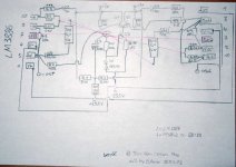
Thx Terry, it really sounds reasonable to lower the voltage (esp. into 4 Ohm load) and i decided to use the PSRR dicrete regulator without global feedback by Pedja Rogic. With 24V AC 350W Transformer and some ordered 22-26V Z-diodes.
juma said:
Gono, don't forget the ground connection - see attachment")
Viel Spass dabei !
Thx alot juma! i fixed that and made the layout a bit more stargrounded & P2P like. Also R14 was 100k instead of 10k in last sheet.
And i found the perfect fitting case, (You will be surprised) the right sized heatsink and i should have all missing parts on my table tomorrow...
Feel free to crosscheck the attached circuit against Terry Aben circuit
Soldering iron will be heated tomorrow.
Thanks all for reply, and stay tuned for pix of hopefully working amp.
ELGono
Attachments
juma said:It looks better now - just 2 things more:
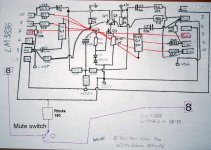
- pin 5 of LM3886 should also be connected to V+
- pin 8 of LM3886 (mute) should have at least 1mA flowing through it (otherwise it won't play)
It's all in datasheet anyway
Thx! the mute switch i had on the switches-drawing, but you're right, they should be included in this drawing too, as well as the Pin 1+5 mark.
R9/11 & R10/12 now also going to starground.
Is it okay to use one switch for all 4 LM3886? The value must be recalculated...
remaining parts will arrive tomorrow as package tracker says.
ELGono
Attachments
Gono said:
Is it okay to use one switch for all 4 LM3886? The value must be recalculated...
Yes, you can. Just take care that every chip gets 1mA through pin 8 - take a separate resistor going from switch to each chip.
Gono said:
Can i use 2 Zener Diodes in Series? like 24V+5V=29V ? is there an order to keep in mind?
Of course you can and order them as you like, but if you want exactly 29V on output of regs you have to account for transistor's Vbe. Take 24V+6V8 zeners - that'll do it.
OTOH, your transformer gives only 24V AC on secondaries. If I were you, my zener would be just one 24V (28V at most) - you'll have to allow for some regulation losses and electrical network instabilities.
Yes, you wrote that you have 33.5V DC unloaded, but it will drop when you turn a volume knob a bit, so it's better to stick with worst case scenario - you don't want any more amps or regs going in the smoke, right ?
nania,
GCSS is basically a bridged amp where every branch of the bridge handles half of the load's impedance. Typical speaker is 8 Ohms, so every chip is handling 4 Ohms load. LM3886 handles 4 Ohms load better than LM3875.
Of course you can use LM3875 in GCSS but your power supply voltage shouldn't go higher than +/- 20 to 22 Volts and only if you have 8 ohms speaker with very flat impedance curve. Otherwise, LM3875 will disappoint you.
juma
Yes, I am aware of the superior current capability of the 3886 but wouldn't using parallel 3875's have more current capability than a single 3886. I thought the 3875 could function on +/-40V, am I mistaken? The 3875 seems much simpler to parallel than the 3886. It is just a notion at this point and I am exploring the potential of these chips from those with more experience so please understand that I am not challenging the choice of the 3886, I am just trying to understand.
Yes, I am aware of the superior current capability of the 3886 but wouldn't using parallel 3875's have more current capability than a single 3886. I thought the 3875 could function on +/-40V, am I mistaken? The 3875 seems much simpler to parallel than the 3886. It is just a notion at this point and I am exploring the potential of these chips from those with more experience so please understand that I am not challenging the choice of the 3886, I am just trying to understand.
Come on nania, you are an old member here - SuSy is just a one diff amp at input and special NFB arangement - Chip Amps section is full of threads about paralleling chips, there are people who used 6 chips per channel. Those threads, datasheets and BPA200 paper will tell you everything
juma
Lots of people are old without knowledge
Seriously, I don't believe those projects use the symmetry noise cancellation but then again, then may not need them. Besides, those projects are for high power amps. I want something with less gain that sounds better and presents a better soundstage. I suspect this may be more easily accomplished with paralleled banks of the 3875. Do you disagree?
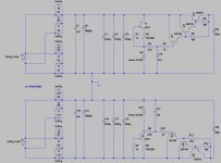
When it comes to using SuSy concept around chips my ears were most satisfied with this circuit (National chips were second to it):
For your application you can use +/- 20 V rails and be happy with 50-60 W / 8 Ohms (even 4 Ohms load don't cause problems - I tested it on my Epos M5 speakers with LT1083 reg. supply for OPA549s). Just be generous with heatsinking if you like playing it loud. OPA 1632 is natural born SuSy diff. amp. and can be pin-to-pin replaced with THS4131 (both Texas instruments). AD797 is just a buffer stage and can be replaced with any buffer of your choice capable of driving 600 Ohms load.
For your application you can use +/- 20 V rails and be happy with 50-60 W / 8 Ohms (even 4 Ohms load don't cause problems - I tested it on my Epos M5 speakers with LT1083 reg. supply for OPA549s). Just be generous with heatsinking if you like playing it loud. OPA 1632 is natural born SuSy diff. amp. and can be pin-to-pin replaced with THS4131 (both Texas instruments). AD797 is just a buffer stage and can be replaced with any buffer of your choice capable of driving 600 Ohms load.
Attachments
juma
That is a very nice regulated supply and I'm sure it sounds very nice but that amp will cost at least three times what I am thinking to make. Remember, I already have the LM3875's so I would like to use them. If you really wanted big power, you could run 8x3875 with +/-56VDC. I think that would sound better and be less problematic to make than an equivalently powered 3886. I don't want to hijack this thread to a non-susy discussion here so I will continue by asking if anyone here has used the 3875 for a GCSS?
That is a very nice regulated supply and I'm sure it sounds very nice but that amp will cost at least three times what I am thinking to make. Remember, I already have the LM3875's so I would like to use them. If you really wanted big power, you could run 8x3875 with +/-56VDC. I think that would sound better and be less problematic to make than an equivalently powered 3886. I don't want to hijack this thread to a non-susy discussion here so I will continue by asking if anyone here has used the 3875 for a GCSS?
juma said:
Yes, you can. Just take care that every chip gets 1mA through pin 8 - take a separate resistor going from switch to each chip.
okidoki, i did so with 4 10k resistors.
juma said:
Of course you can and order them as you like, but if you want exactly 29V on output of regs you have to account for transistor's Vbe. Take 24V+6V8 zeners - that'll do it.
OTOH, your transformer gives only 24V AC on secondaries. If I were you, my zener would be just one 24V (28V at most) - you'll have to allow for some regulation losses and electrical network instabilities.
Yes, you wrote that you have 33.5V DC unloaded, but it will drop when you turn a volume knob a bit, so it's better to stick with worst case scenario - you don't want any more amps or regs going in the smoke, right ?
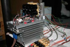
Well good news first: it's up'n'running
It nearly took a week, but it was worth it! I still need to finish the chassis, it will look great and i hope to finish this project this weekend! Pictures will be updated then.I build it with 24V Zeners and get about +/- 23,8V (both rails nearly same value). It was build strict P2P mounted directly on a (way too huge) heatsink. The heatsink i wanted to save for the "amazing circlotron" but as i don't have money for a set of new transformers atm i decided to try this "cheaper" project first. And so far i'm not disappointed. The midrange is really clear and but not too analytic as i can tell from still "burning in" the amp. I was missing some bass when driving it with symmetric input, but i just had an isolating transformer for symmetrie generation so far and think that was the reason. Then i changed to asymmetric input wich gave a bit more pressure in lower frequencies but at cost of midrange detail. But i don't want to bore you with sounding impressions of an amp, wich is still formattig its electric soul.
But with asymmetric inputs another problem occoured: The amp went into clipping quite fast! I did not ran it extremly loud (couch was not vibrating) and i was wondering why. As i mentioned i use 4 Ohm speakers (Nubert 380's // 2 way compact-speakers) with impedance-linearization, wich like to suck some current.
So there are 2 more questions for improving the circuit to my environment: If my impedance does not went much below 4 Ohms, should i increase the voltage by using 25-28V zeners? Hope to get some Zeners tomorrow to answer the question myself... but opinions are welcome. Datasheet says increasing supply voltage from 23 to 27 V should increase output power from approx. 42 to some 70's VA as well as the clipping voltage should went up 0.5V
(Yea i know, it's the first watt that counts and i believe in that)
The other idea i had was changing C1/2 1uF to 3.3uF ...
Best of course would be to bring in the 2 E88CC tubes for symmetry creation, wich maybe solves the clipping problem best way, but means another week of soldering and case-modding wich i should dicuss with my girlfriend first
....attached a pic of first test run and you'll find some more (full res.) in the gallery
Thank all of you for supporting!!! and keep building amps!
ELGono
Attachments
Gono said:
... The amp went into clipping quite fast! I did not ran it extremly loud (couch was not vibrating) and i was wondering why. As i mentioned i use 4 Ohm speakers ...
Your amp's clipping is induced by current limiting circuit inside the chip because GC SuSy is bridge amp so each of your chips is actually driving a 2 Ohms load. Don't increase the PS voltage - it will make things worse. IME +/- 20V PS voltage is the highest safe voltage for bridge-tied LM3886 when driving 4 Ohms speakers. Otherwise, you are asking a LM3886 to give more than 60W and current-limiting circuit causes clipping.
If you want more power and higher PS voltage do the stuff from BPA-200 (National semiconductor application note) and prepare larger heatsinks and transformers.
Rodeodave said:Wow, incredible design. Dead Bug Deluxe.
Did you do sketches on paper first to get the proportions or did you solder en route? Echt geil.
Indeed, think i should put some varnish on as final step to save bugs life!
And yes, i planned the layout on paper as the complete circuit. Wanted to do it 0ld5k3wl like back in the days without pspice flavour. (besides circuit was discussed/calculated in detail in this thread)juma said:
Your amp's clipping is induced by current limiting circuit inside the chip because GC SuSy is bridge amp so each of your chips is actually driving a 2 Ohms load. Don't increase the PS voltage - it will make things worse. IME +/- 20V PS voltage is the highest safe voltage for bridge-tied LM3886 when driving 4 Ohms speakers. Otherwise, you are asking a LM3886 to give more than 60W and current-limiting circuit causes clipping.
If you want more power and higher PS voltage do the stuff from BPA-200 (National semiconductor application note) and prepare larger heatsinks and transformers.
Well, so far i understood the principle of bridged amp, but i'm still not sure what happens when driving it with unbalanced inputs. I was thinking this way:
the negative input is directly going to ground wich leaves all the work to just one LM3886 while his negative brother is out of work. In that case it should handle the complete 4 Ohm load, not just the half of it. But i'm not sure about it anymore... A single LM3886 should deliver some 40VA at 24V wich means ~1.6A current delivery ... way below clipping range... so my thinking must be wrong! Sounds like some more studies on SuSy to me.
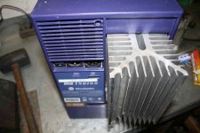
But anyhow, i tried different di-units for balanced input wich solved the problems! Really nice sounding now and enough power for termination of my flat-lease
Maybe the first ones were just lo-fi.So i think i can leave the circuit as it is right now... just an unbalanced to balanced converter will be added soon, cause my "B1 Buffer Pre" (P2P as well) is unbalanced. But first i need to finish the case modding ... i attached a little appetizer
thx again juma for explanations
ELGono
Attachments
- Status
- This old topic is closed. If you want to reopen this topic, contact a moderator using the "Report Post" button.
- Home
- Amplifiers
- Pass Labs
- GC SuperSymmetry