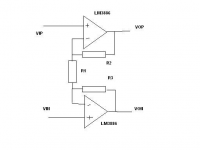
Not quite. The LM6181 is a current feedback device, but in
this case you would have to ties the inverting inputs together,
drive the non-inverting inputs, and amplify the output with
a negative phase (the power chips following the LM6181 would
be set up as inverters). The inversion reverses the effective
polarity of the LM6181's inputs.
this case you would have to ties the inverting inputs together,
drive the non-inverting inputs, and amplify the output with
a negative phase (the power chips following the LM6181 would
be set up as inverters). The inversion reverses the effective
polarity of the LM6181's inputs.
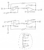
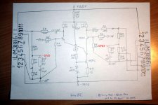
TFTR. Does the attached capture your comments?
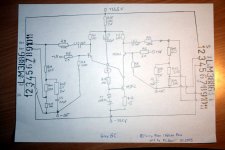
Also, since I barely understand CFB opamps let alone VFB opamps, does trying to make a good differential stage with CFB opamps, where the inverting input is low impedance, force you to add a CCS as shown in the dotted circle, or is this plain nonsense?
Also, since I barely understand CFB opamps let alone VFB opamps, does trying to make a good differential stage with CFB opamps, where the inverting input is low impedance, force you to add a CCS as shown in the dotted circle, or is this plain nonsense?
Attachments
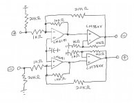
Use something more like 10K input resistors instead of 100, as
the + input junctions will be operating at virtual ground. With
the 50K feedback values, the gain would be 15 dB.
As noted before the input op amps will be "current feedback"
types, and you can eliminate their 1k feedback resistors and
use any arbitrary value between their - inputs, as low as 0.
the + input junctions will be operating at virtual ground. With
the 50K feedback values, the gain would be 15 dB.
As noted before the input op amps will be "current feedback"
types, and you can eliminate their 1k feedback resistors and
use any arbitrary value between their - inputs, as low as 0.
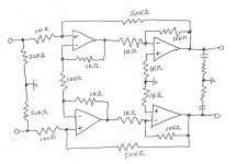
Nelson Pass said:..... I present a concept schematic
which uses power chips such as
the LM3875 or LM3886
Thanks Nelson.
Have a nice day.
I will now contemplate deeply your new schematic!
then I'll go back to sleep in my sweet sweet dreams
to give my brains a good rest and recovery (not fast recovery .. but slow)

Ahoi
after nearly missing midnight on december 31. -lost in reading this 653 posts thread- i decided to build this amp. (one reason: i liked the process of development in this forum very much) I still have an unregulated 33,5 VDC PS from my last amp project, wich went up in smoke few days ago after a year of nice sounding.
Because of this high supply voltage i choosed metalmans design and as i use 4 Ohm speakers i refer to post #439 with the corrections.
there is on offer in post #442
@metalman:
is this offer still valid for a 33,5 VDC supply?
I'm still thinking of modifications into a regulated supply wich maybe lowers the voltage a bit, but as i tend to use carlosfm's "snubberized" there is not much hope to lower it.
Instead of ZTX450's i could use BD139 or even better MPSA42. Need to use spare parts as long as i'm student
Apropos spare parts... i still got 2 E88CC aka 6922 wich i really should invoke in this project. Post #271 looks interesting and just needs an delayed relay for tubes heating up.
Another idea is to use them for symetrie creation when using asymetric inputs instead of on DRV137. If i bring it on paper this weekend, i'll post it for disussion.
Just one last note: metalman, you really made my day writing:
i nearly forgot about new years beginning and my waiting girlfriend while reading this thread. And it was not the first time, i had a soldering- or circuit planning fever. Thank all you guys so much for sharing and discussing ideas. I sometimes thinks, it's like making music in a jam... and the music itself is "music-reproduction-circuit-poetry".
Happy New Year diy'ers
ELGono
after nearly missing midnight on december 31. -lost in reading this 653 posts thread- i decided to build this amp. (one reason: i liked the process of development in this forum very much) I still have an unregulated 33,5 VDC PS from my last amp project, wich went up in smoke few days ago after a year of nice sounding.
Because of this high supply voltage i choosed metalmans design and as i use 4 Ohm speakers i refer to post #439 with the corrections.
there is on offer in post #442
metalman said:Kari,
After additional checking, if you wish for convenience sake, you can make R9 and R10 500 ohm resistors too. It is less "optimal" but I don't beliieve that it will make an audible difference.
Also, for everyone else, I have realized that the values for the resistors are very dependant on the voltage of the power supply rails. The values I posted are valid in the 29-31 volte range. The good news is that I can now determine the optimum values relatively easily for any range of supply voltage. If you need values for a different set, let me know.
@metalman:
is this offer still valid for a 33,5 VDC supply?
I'm still thinking of modifications into a regulated supply wich maybe lowers the voltage a bit, but as i tend to use carlosfm's "snubberized" there is not much hope to lower it.
Instead of ZTX450's i could use BD139 or even better MPSA42. Need to use spare parts as long as i'm student
Apropos spare parts... i still got 2 E88CC aka 6922 wich i really should invoke in this project. Post #271 looks interesting and just needs an delayed relay for tubes heating up.
Another idea is to use them for symetrie creation when using asymetric inputs instead of on DRV137. If i bring it on paper this weekend, i'll post it for disussion.
Just one last note: metalman, you really made my day writing:
metalman said:
Damn you Nelson Pass!!! Before I found passdiy.com I was content with my ignorance and mediocre sounding stereo system. No one warned me that this hobby is an infectious disease causing a slow spiral into insanity. I spend way too much time now giggling uncontrollably while surrounded by electronics paraphenalia, murmering about the search for the ultimate circuit.
i nearly forgot about new years beginning and my waiting girlfriend while reading this thread. And it was not the first time, i had a soldering- or circuit planning fever. Thank all you guys so much for sharing and discussing ideas. I sometimes thinks, it's like making music in a jam... and the music itself is "music-reproduction-circuit-poetry".
Happy New Year diy'ers
ELGono
Hey Gono,
can you post some pics when you get the chance as well as the schematic you settle on.
i am really curious about your impressions when you get it up and running
i ordered the parts for this project a while back but have not had time to implement. hopefully i will find the time soon.
good luck
Tim
can you post some pics when you get the chance as well as the schematic you settle on.
i am really curious about your impressions when you get it up and running
i ordered the parts for this project a while back but have not had time to implement. hopefully i will find the time soon.
good luck
Tim
okapi said:Hey Gono,
can you post some pics when you get the chance as well as the schematic you settle on.
i am really curious about your impressions when you get it up and running
...
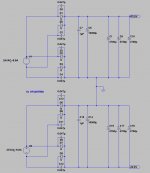
sure, i just finished the Spaghetti design with parts i have available. I attached a file how it should look like. I have MPSA42 or BD139 hope i can use them... think i have to start up ltspice to have a closer look.
After reading the LM3886 datasheet, i really should lower the voltage a bit. 67V across both rails is too much for 4 Ohm speakers.
I'll get that topic on the drawing board next. But i'm open minded for any suggestions too.
ELGono
Attachments
Gono said:I still have an unregulated 33,5 VDC PS from my last amp project, wich went up in smoke few days ago after a year of nice sounding.
Does 33,5 VDC mean 33 VDC @ 5 (max) amps?
Apologies for the noob question. I'm just getting into this DIY stuff and I get lost trying to keep up.
I hope this doesn't sound lazy, as in I don't want to bother calculating another set of resistor values, but for anything above 29V, the resistor values can be left alone, as the chips will clip before the rest of the circuit will.
If you want to burn a little voltage, you can always regulate the powersupply. Personally, I liked the amp better with a regulated supply, but others have differeing opinions.
Whichever way you decide to go, this will be a substantial step up from the mid-fi commercial stuff.
I still have plans to put out a couple of other higher current output capable versions, but career has interfered with my availability of time. Still haven't finished my usb-dac project for lack of time to etch some fine detailed boards!
That being said, I'll still provide as much help as I can within the time constraints, so feel free to ask.
Cheers, Terry
faiyaza said:
Does 33,5 VDC mean 33 VDC @ 5 (max) amps?
Apologies for the noob question. I'm just getting into this DIY stuff and I get lost trying to keep up.
nope, means 33.5 V DC ... just european writing instead of dot as seperator.
Attached the circuit of the PS as it looks like at moment.
Transformator is a torroid with 2x 24V AC @ 6.8A secondaries.
the 2x 10000uF caps are not included right now, but are going in for this project.
with idle load of 200mA i measure +/- 33.5 V @ output.
just looking at "Pedja Rogic's regulated supply" wich metalman mentioned. Next to that i search in the box of transistors to find a solution i can bring on for discussion.
ELGono
Attachments
- Status
- This old topic is closed. If you want to reopen this topic, contact a moderator using the "Report Post" button.
- Home
- Amplifiers
- Pass Labs
- GC SuperSymmetry