No. I think it might be in TI app sheet, but he did excellent job explaining it. Fiddlin with id on preamp, among other things. Seems too complicated, but i am thinking i lack understanding. Whitlock for Jensen also has nice right up on similar. THink it is what is found inside THAT chips. Trying to get away from TOshibas and use BF862 or sk369 in FE of LTP with. Oh who cares
Thanks for looking. Ill try Wensan.
Thanks for looking. Ill try Wensan.

I wonder about BF862 drive capabilty. It is on par with 369 for noise. I tinhk have some J309. Just trying to use more common parts. Looking at maybe a unity gain version of funny amp, as after heating BA3B(feedback version) with F6 and other amps, I do not really need much, if any gain and that was on 88dB speakers. Altec will do 110dB at 10-12w.
use CCS for biasing , so no worry about Ugs ;
309 is same as 310 , just selected for lower Idss
current - pretty same as for Toshibas , keep Uds in range of 12-15V and you're good dissipation wise
cascode if needed
so - no worry about driving capability
for 309/310 - take a look at , for BF862 take a look at Juma's circs
309 is same as 310 , just selected for lower Idss
current - pretty same as for Toshibas , keep Uds in range of 12-15V and you're good dissipation wise
cascode if needed
so - no worry about driving capability
for 309/310 - take a look at
, for BF862 take a look at Juma's circs
I just realized it looks like the Pumkpin
I will post idea soon. Have more reading to do.
It is based on my fancy of the Salas Riaa. A common drain gain stage, loaded with folded cascode. Mine will probably feed a buffer and will be a blanced i some way. Just swirling around in my one cell right now.
I will post idea soon. Have more reading to do.
It is based on my fancy of the Salas Riaa. A common drain gain stage, loaded with folded cascode. Mine will probably feed a buffer and will be a blanced i some way. Just swirling around in my one cell right now.

I am also interested in balanced amps employing distortion cancellation. where are you going with it?I have images of McMillan resistors floating in my head. Very little(if anything) new under the sun.
I am toying with a balanced amp which uses a mechanism for cancellation of distortion. It has a unique subjective performance. A tight low end and especially a clear and detailed higher end. I flash-read through the posts; but did not get a feel from DIYers for the subjective performance of their amps per the concept design of Mr. Pass of post 1. Any comments on this!Already listening to crude version. This FE of power amp that I am trying as pre. Official pre is coming up, but I am trying to better understand things.
I will not be using opamps, a departure from this thread, but was looking for a good explanation of fully differential setups. I am looking for really clean preamp with minimal, if any, CLF.
[Su-Sy is an approach that takes advantage of balanced operation like
no other design, and requires a balanced input to retain the precisely matched behaviour. You can drive one input alone, and the circuit willamplify reasonably well, but it will not exhibit the very low distortion character of fully balanced operation.]
no other design, and requires a balanced input to retain the precisely matched behaviour. You can drive one input alone, and the circuit willamplify reasonably well, but it will not exhibit the very low distortion character of fully balanced operation.]
The above is an excerpt from Mr. Pass's article on SuperSymmetric amplification. One must use a balanced input as he taught above. If one does not, but drives one input alone, the resulting amp will not deliver very low distortion.
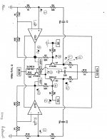
The following schematic is by metalman [T. Aben]. I superimposed on it the half shaded sinewave caricatures in order to visually [a la Pass] show the effect of driving one input alone [e.g. Right amp]. Follow the numerical sequence [1-10] on the caricatures with particular focus on their phase. I hope it'll help your work. Note that I grounded the negative Input.
- Signal 9 must be of opposite phase than written.
- It is amplified by Q1 and shows up as signal 10.
- Signal 6 and 10 cancel fully or partially; because they are out of phase.
- The left chip now receives at best a low level signal [7] to give a low level output signal at +Out [8].
- The phase of the Out signals are correct; but the magnitude of the signal at negative Out [4] is much higher than that at positive Out; which may be zero in value; if signals 6 and 10 fully cancel each other.
- Thus the Left amp works as a current sink [virtual ground] to the Right amp.
- The net amp is not balanced or one is operating the right amp only with its intrinsic distortion.
The resultant amp complies with "the resulting amp will not deliver very low distortion."
Attachments
I will not be using opamps, a departure from this thread, but was looking for a good explanation of fully differential setups. I am looking for really clean preamp with minimal, if any, CLF.[/QUOTE]
You have revived a thread which went stale in July 2011! The schematic in the first post by Mr. Pass and that of metalman in my previous post are the same. They show CLF [closed loop feedback] around the diff amp made with the discrete components. This loop closure is essential for cancellation of distortion. The schematics will still work if the power amp under test [PAUT; e.g. instead of the chip amp] does not require its own feedback loop; and does not invert phase as shown.
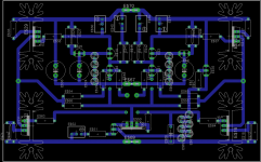
I'll decipher your pcb. Best regards
STASIS[R]+SuperSymmetry
Best regards
It is a balanced THRESHOLD S/150 power amp using the SuperSymmetry lessons in this thread. Is there an amp which tops the performance of this combination? Schematic to follow.For those who didn't find "Monolithic SuperSymmetry" interesting
enough, I present a concept schematic which uses power chips
such as the LM3875 or 3886 (or anything else, for that matter).
Best regards
STASIS[R] Plus SuperSymmetry
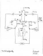
The schematic is attached. The diff amp was assembled on a Protoboard. The following are the setup rules to establish stable operation.
The above protocol was also practiced on the chip amp LM386 [100 milliWatt], a Realistic STA2000D [75W/Ch into 8Ohm] with equal success. I'll post performance details.
It is a balanced THRESHOLD S/150 power amp using the SuperSymmetry lessons in this thread. Is there an amp which tops the performance of this combination? Schematic to follow.
Best regards
The schematic is attached. The diff amp was assembled on a Protoboard. The following are the setup rules to establish stable operation.
- No load to the power amps.
- Start with 100 Ohm load resistors to the diff amp
- Turn on the power amp
- Check for a high frequency oscillation at both power amp outputs
- If no oscillation, turn off power amp and increase the value of the diff amp load resistors to 120 Ohm.
- Repeat this sequence with increasing valued resistors; e.g. 150, 180, 220, 270 Ohm until the amp breaks into oscillation.
- Back off to the lower valued resistor where no oscillation was observed.
- Connect a dummy resistive load, and power up the amp. The amp
will not oscillate.
[*]Disconnect the resistive load and connect a loudspeaker. The R and L ampwill not oscillate.
[*]Enjoy music.
Attachments
- Status
- This old topic is closed. If you want to reopen this topic, contact a moderator using the "Report Post" button.
- Home
- Amplifiers
- Pass Labs
- GC SuperSymmetry